| “This site contains affiliate links for which OEMDTC may be compensated” |
NHTSA Campaign Number: 16V334
Component(s): AIR BAGS
Potential Number of Units Affected: 38,628
Manufacturer: Mitsubishi Motors North America, Inc.
SUMMARY:
Mitsubishi Motors North America, Inc. (MMNA) is recalling certain model year 2006-2007 Lancer and Lancer Evolution vehicles manufactured June 29, 2005, to June 19, 2007, equipped with certain air bag inflators assembled as part of the passenger frontal air bag modules, and used as original equipment or replacement equipment.
In the event of a crash necessitating air bag deployment, these inflators may rupture due to propellant degradation occurring after long-term exposure to absolute humidity and temperature cycling.
CONSEQUENCE:
An inflator rupture may result in metal fragments striking the vehicle occupants resulting in serious injury or death.
REMEDY:
MMNA will notify owners, and dealers will replace the passenger frontal air bag inflator, free of charge.
The manufacturer has not yet provided a notification schedule.
Owners may contact MMNA customer service at 1-888-648-7820.
MMNA’s number for this recall is SR-16-002.
NOTES:
Owners may also contact the National Highway Traffic Safety Administration Vehicle Safety Hotline at 1-888-327-4236 (TTY 1-800-424-9153), or go to www.safercar.gov.
Check if your Mitsubishi has a Recall
| SUBJECT:
LANCER PASSENGER SIDE FRONTAL AIR BAG INFLATOR – SAFETY RECALL CAMPAIGN |
No: SR-16-002 | ||||||||||||||||||
| DATE: July, 2016 | |||||||||||||||||||
| MODEL: 2006-07 Lancer | |||||||||||||||||||
PURPOSE
This campaign bulletin instructs dealers to replace the passenger side frontal air bag inflator with a dessicated one, and return the subject air bag inflator per the instructions at the end of this bulletin.
BACKGROUND
Based upon a Defect Information Report submitted to the National Highway Traffic Safety Administration by TK Holdings (Takata), MMNA is recalling certain 2006-2007 Lancer vehicles.
Affected vehicles are equipped with a specific type of passenger side frontal air bag inflator provided by Takata that could be susceptible to rupture, due to excessive internal pressure, during a normal air bag deployment event. This condition is more likely to occur if the vehicle has been exposed to high levels of absolute humidity for an extended period of time.
AFFECTED VEHICLES
2006 – 2007 Lancer
CUSTOMER NOTIFICATION
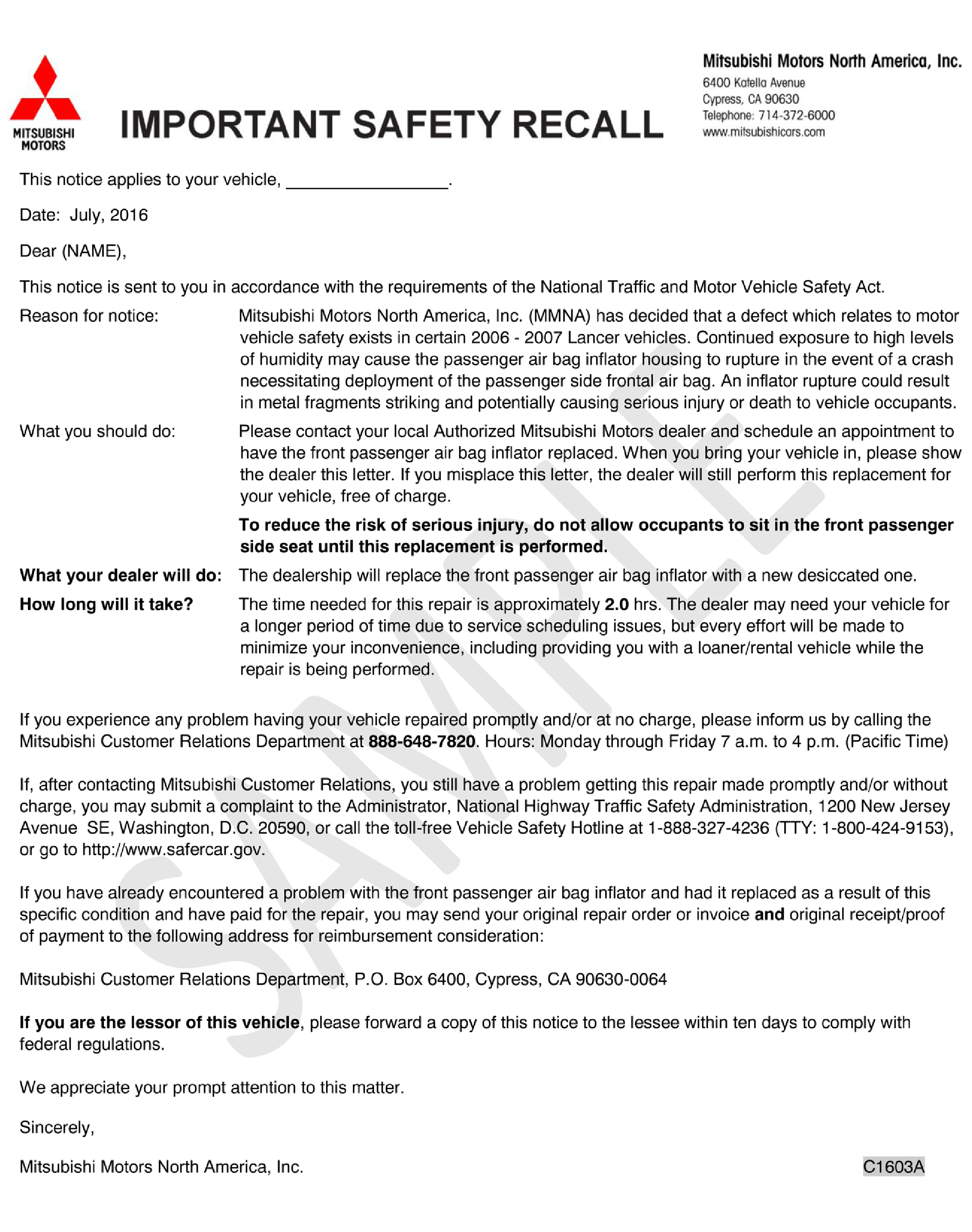
A letter will be sent to all owners of affected vehicles telling them to visit their local Authorized Mitsubishi Motors dealer to have the passenger side frontal air bag inflator replaced. A sample customer notification letter appears at the end of this bulletin.
REQUIRED OPERATIONS
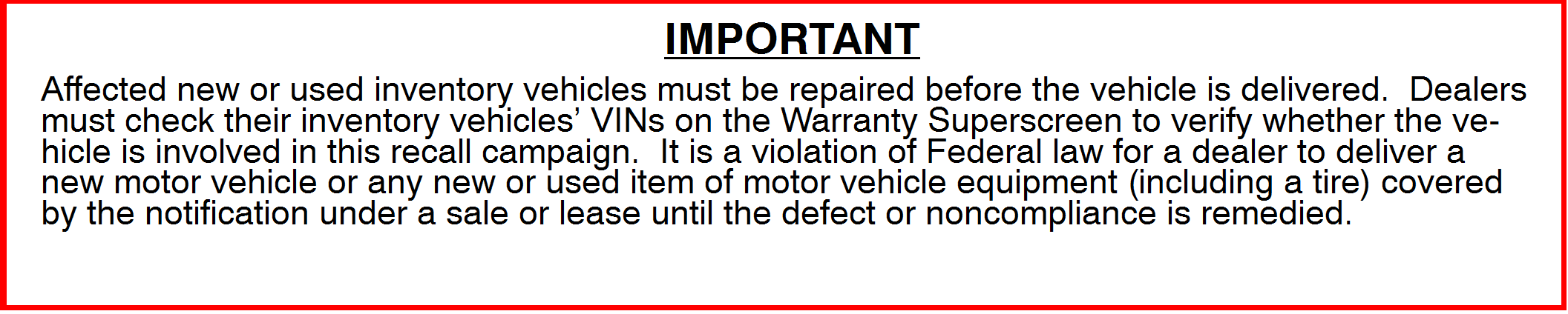
Before starting this campaign procedure, CHECK THE WARRANTY SUPERSCREEN to verify if the vehicle is an affected VIN for this campaign and that this campaign procedure has not already been completed.
REQUIRED EQUIPMENT
- VCI (Vehicle Communication Interface) or VCI Lite – MB991824 or MB992744.
- MEDIC Laptop/Tablet with A/C power adapter – 520924, or 547708.
- MUT-III main harness ‘B’ (red or black connector at the DLC end) – MB991911 or MB992746.
- USB 2.0 cable – MB991827 or MB992747.
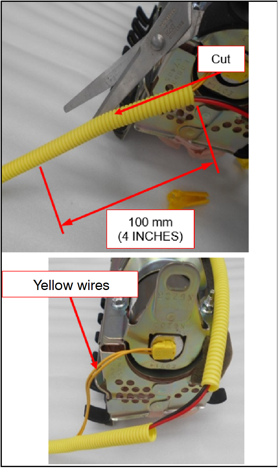
- Scissors
REMOVAL PROCEDURE
![]() Before starting work, and periodically while working on the vehicle, touch a metallic part of the vehicle to discharge static electricity.
Before starting work, and periodically while working on the vehicle, touch a metallic part of the vehicle to discharge static electricity.
![]() Never attempt to disassemble or repair the air bag modules or clock spring. If faulty, replace it.
Never attempt to disassemble or repair the air bag modules or clock spring. If faulty, replace it.
![]() Do not drop the air bag modules or clock spring or allow contact with water, grease or oil. Replace it if a dent, crack, deformation or rust is detected.
Do not drop the air bag modules or clock spring or allow contact with water, grease or oil. Replace it if a dent, crack, deformation or rust is detected.
![]() The air bag modules should be stored on a flat surface and facing upward. Do not place anything on top of it.
The air bag modules should be stored on a flat surface and facing upward. Do not place anything on top of it.
![]() Do not expose the air bag modules to temperatures over 93o C (200o F).
Do not expose the air bag modules to temperatures over 93o C (200o F).
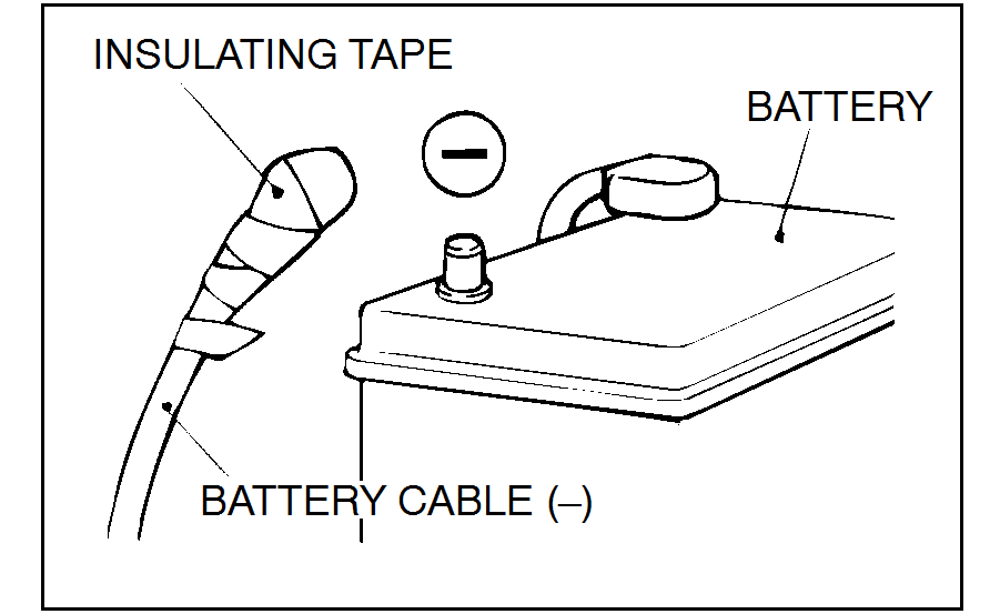 |
![]() Wait at least 60 seconds after disconnecting the battery cable before doing any further work to prevent accidental air bag deployment.
Wait at least 60 seconds after disconnecting the battery cable before doing any further work to prevent accidental air bag deployment.
![]() Battery posts, terminals, and related accessories contain lead and lead compounds. WASH HANDS AFTER HANDLING.
Battery posts, terminals, and related accessories contain lead and lead compounds. WASH HANDS AFTER HANDLING.
 |
|
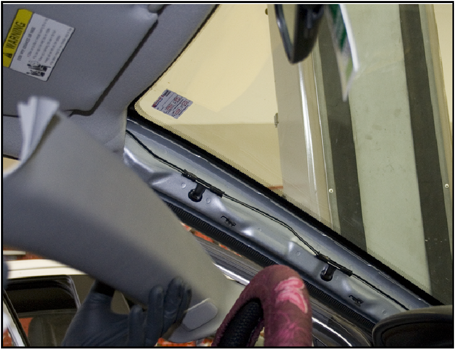
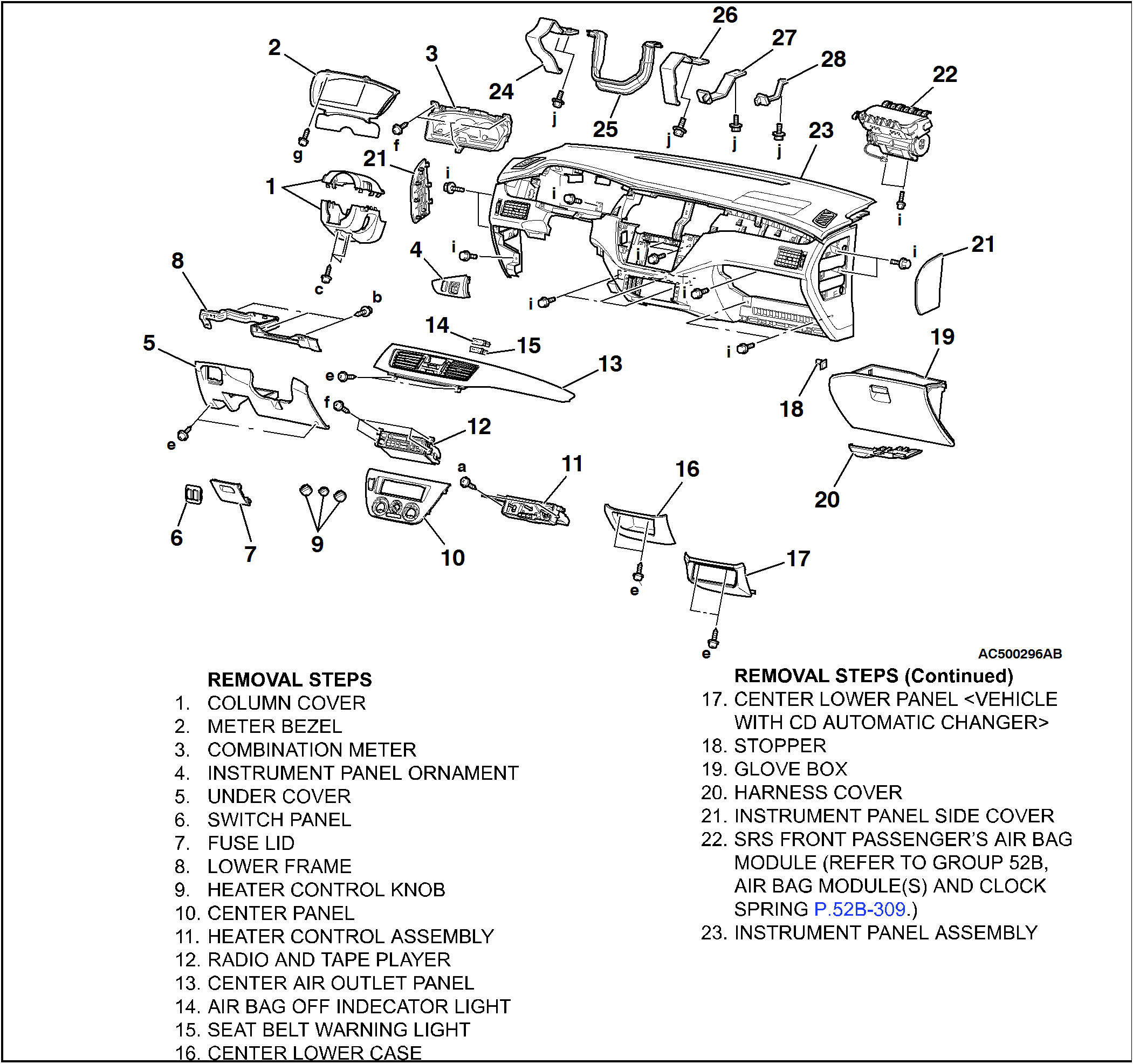
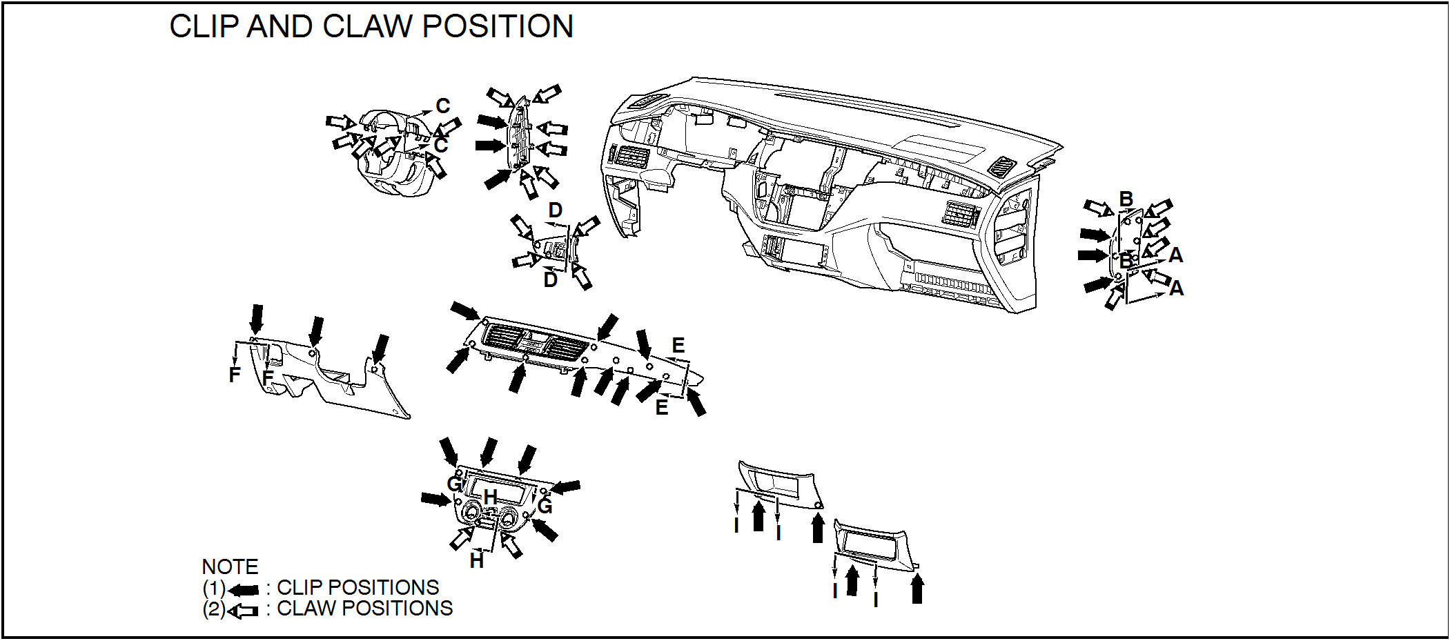
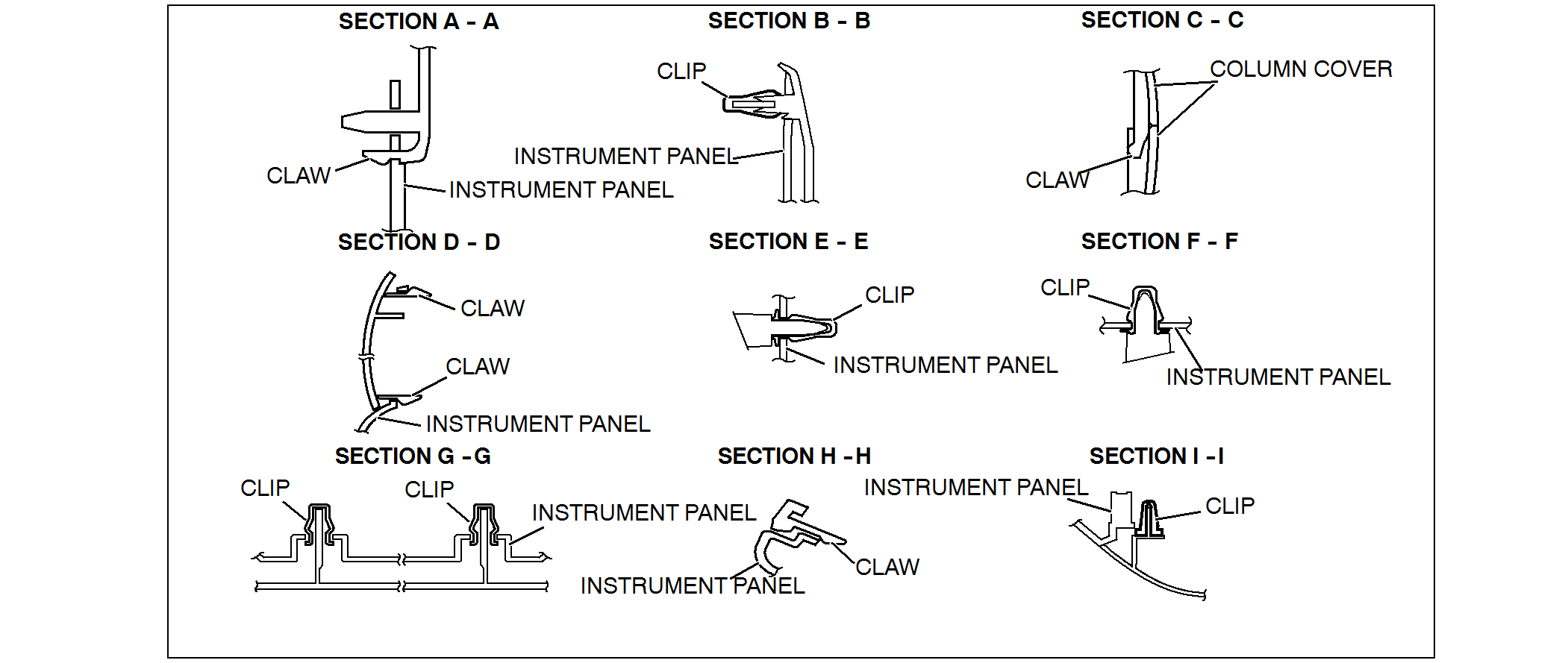
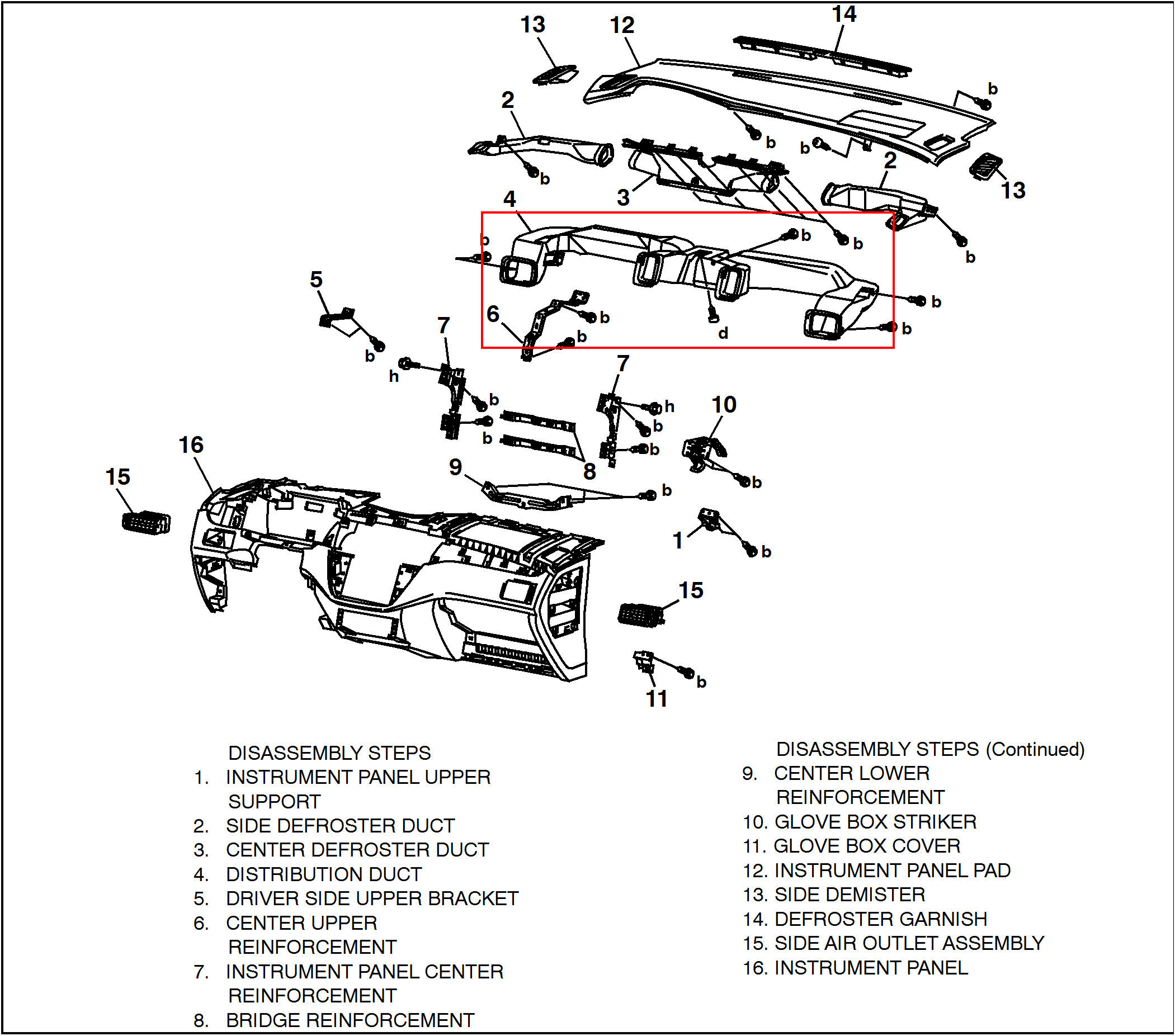
- Remove the instrument panel.
 |
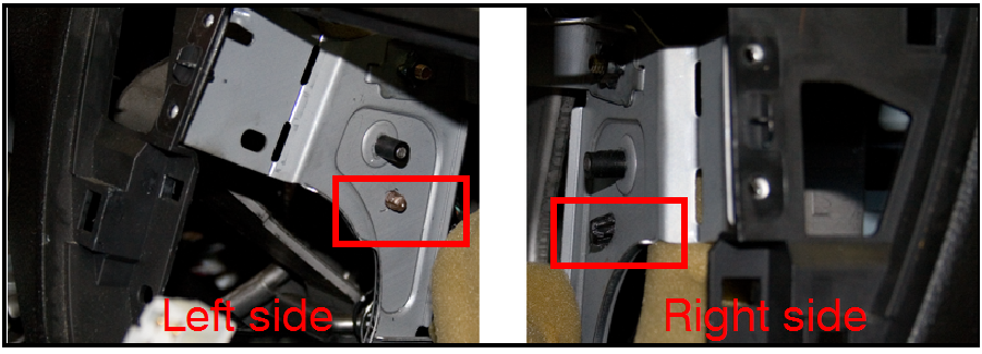 |
NOTE: Make sure the left and right wire harness clips, behind the radio, are disconnected prior to dash removal. |
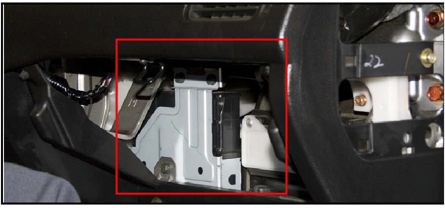 |
NOTE: Unbolt the ECM/PCM prior to dash removal. |
 |
|
 |
|
- Remove the distribution duct from the instrument panel.
 |
![]() Do NOT damage the air bag or the instrument panel during air bag module removal.
Do NOT damage the air bag or the instrument panel during air bag module removal.
INFLATOR REMOVAL
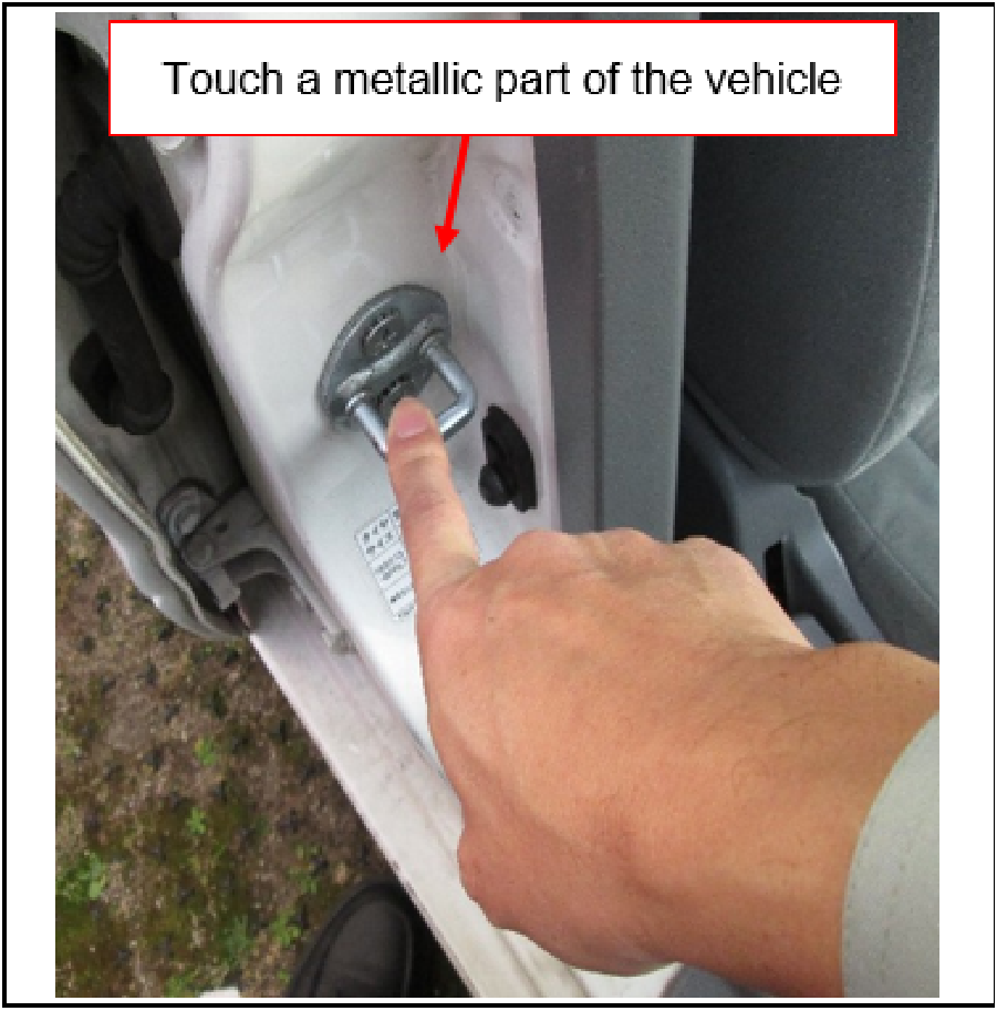 |
CAUTION: ELIMINATE STATIC ELECTRICITY Before starting work, and periodically while working on the vehicle, touch a metallic part of the vehicle to discharge static electricity. |
 |
|
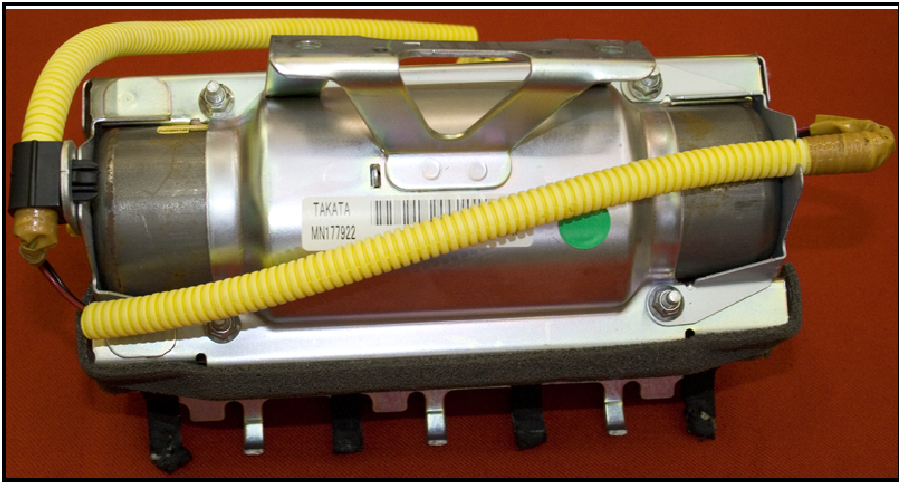 |
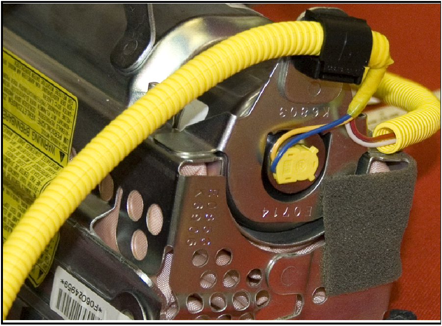
![]() The air bag module, and especially the air bag component, must be protected from adhesive, dirt, dust and sharp items.
The air bag module, and especially the air bag component, must be protected from adhesive, dirt, dust and sharp items.
The protective foam on the air bag module may be brittle. Ensure foam debris is immediately removed from the work area to maintain a contaminant-free work environment.
 |
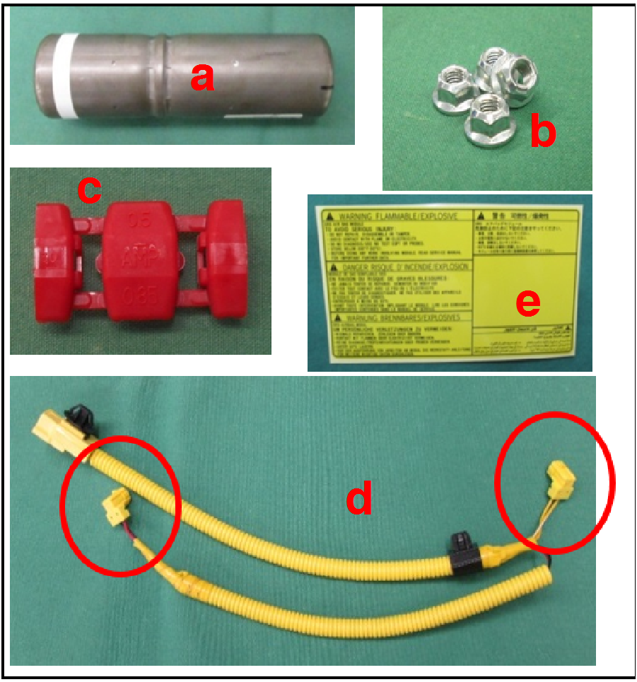
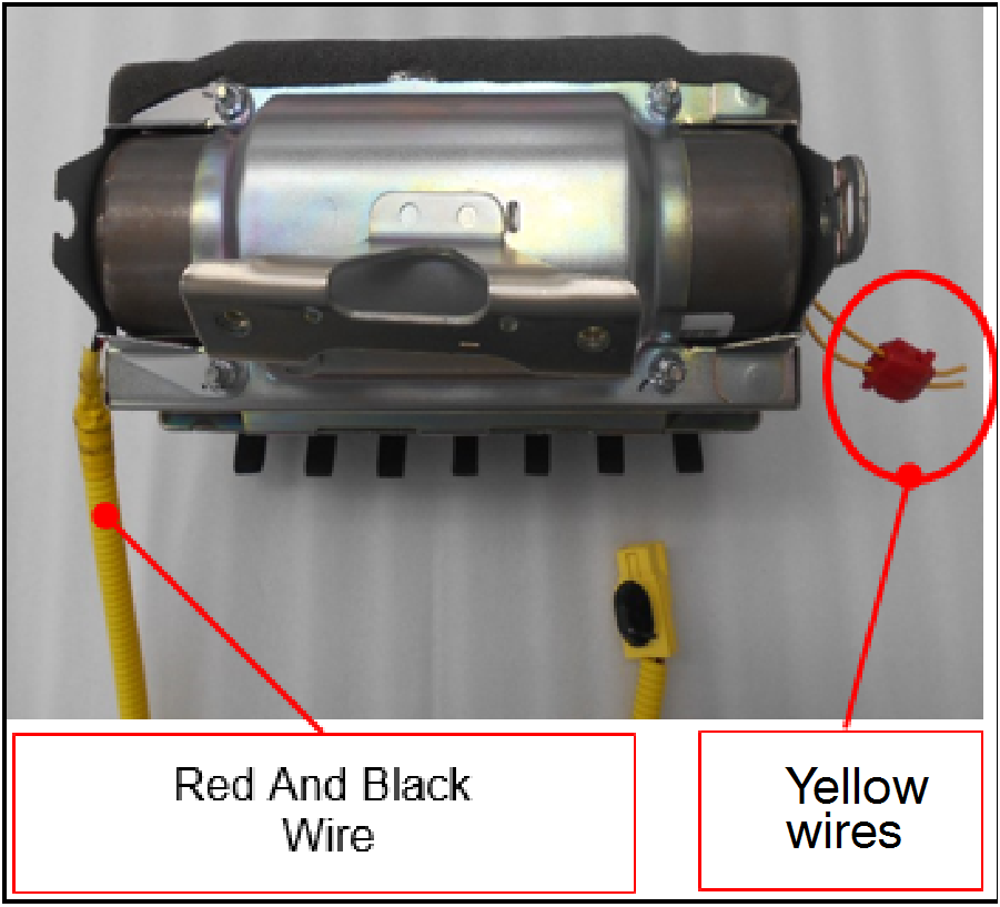
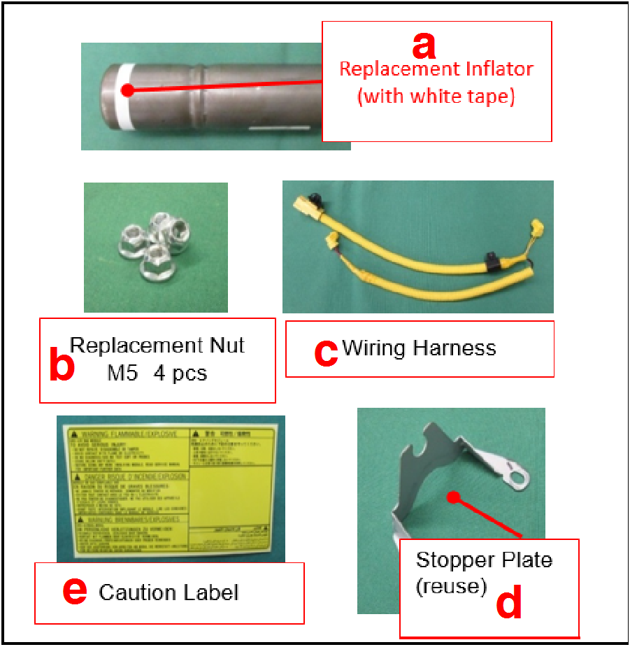
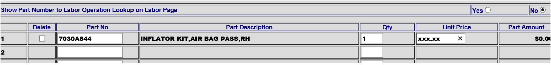
Air bag Inflator Kit Part No.: 7030A844
|
 |
|
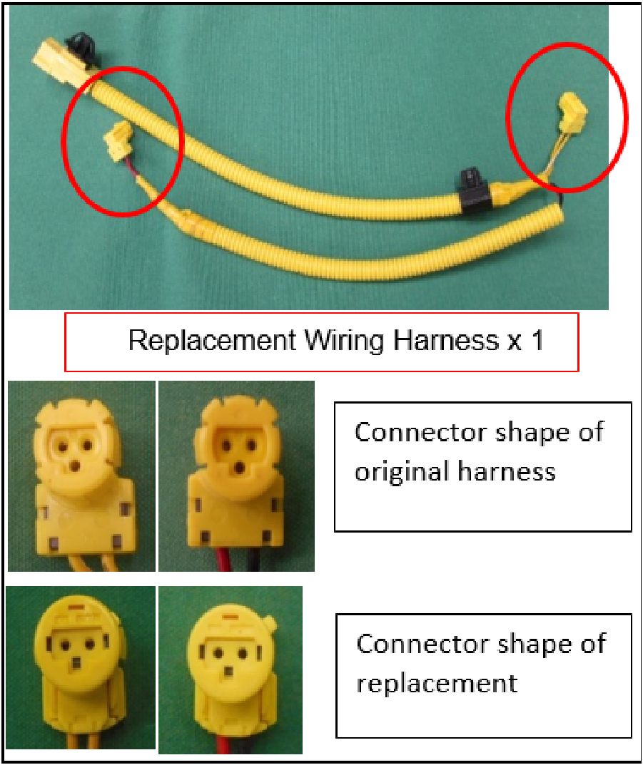 |
NOTE: The replacement wiring harness’ connector is different from the original connector. However, the two are compatible. The replacement wiring harness has the same function and performance as the original. |
 |
|
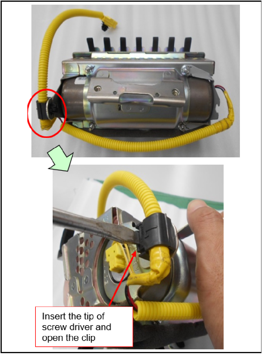 |
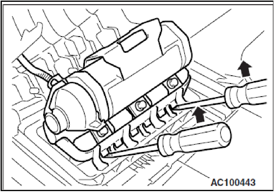
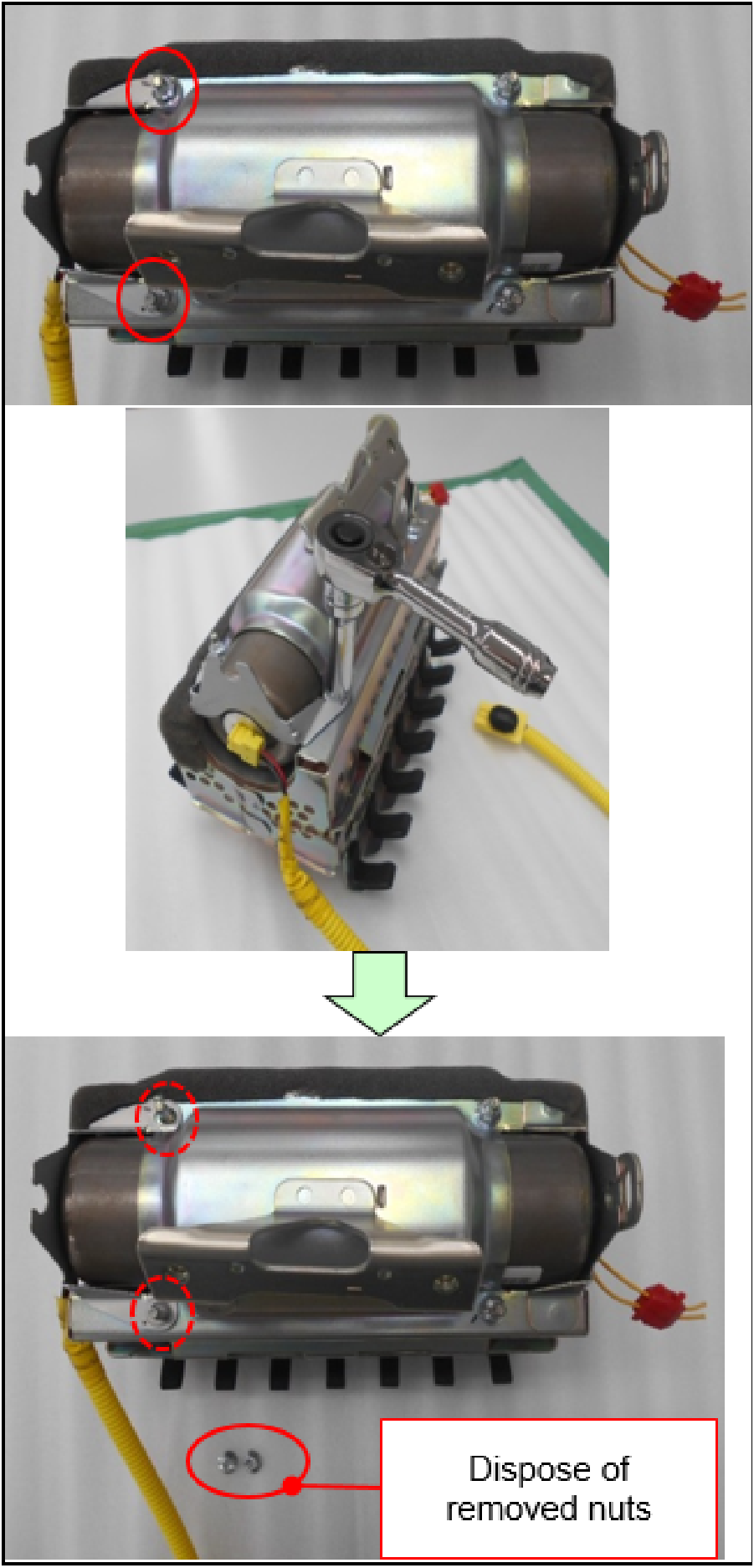
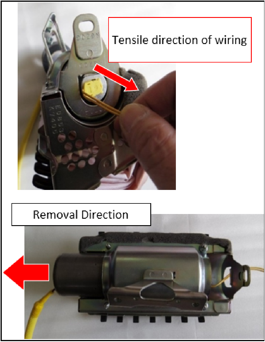
CAUTION: Do NOT damage the harness or air bag with the screwdriver. |
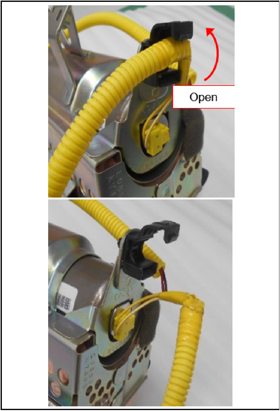 |
|
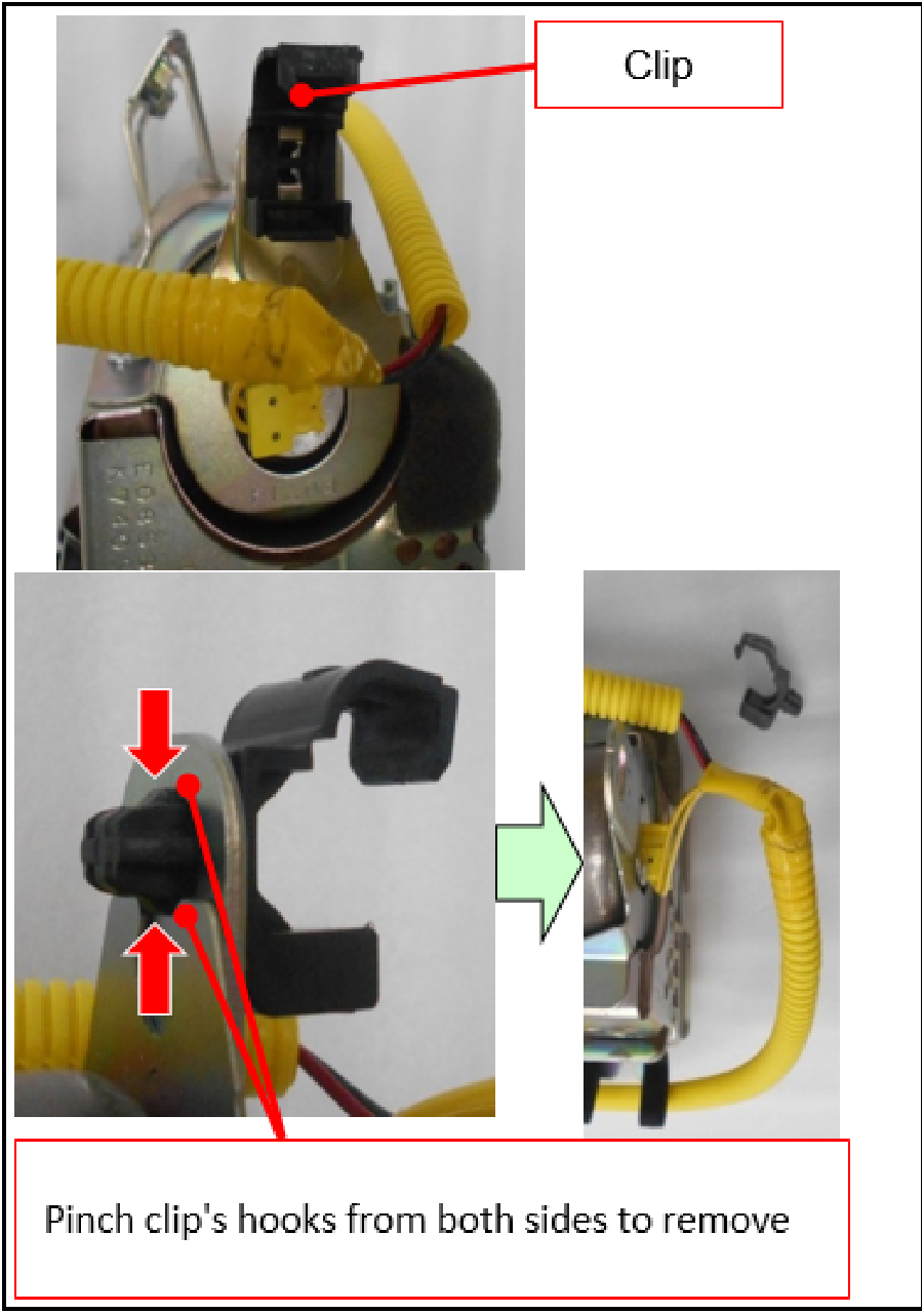 |
NOTE: Since the wiring will not be reused, the clip is not required to be undamaged during removal. |
 |
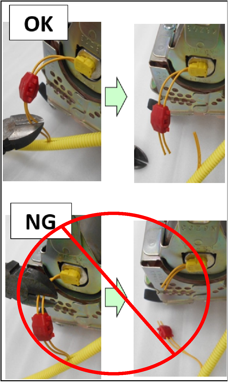
WARNING: Strictly follow all instructions to avoid accidental air bag deployment.
CAUTION: |
 |
WARNING: Strictly follow all instructions to avoid accidental air bag deployment.
CAUTION:
|
 |
|
 |
|
 |
|
 |
|
 |
WARNING: |
 |
|
 |
CAUTION: |
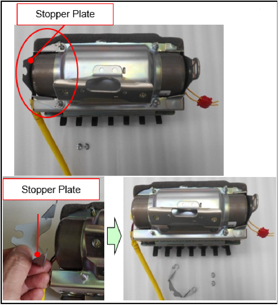 |
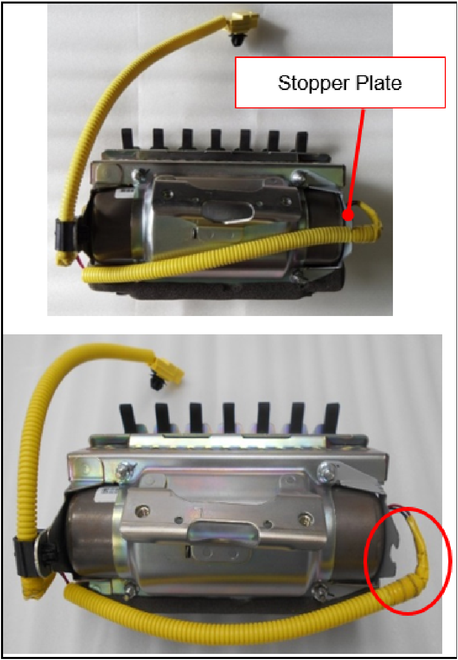
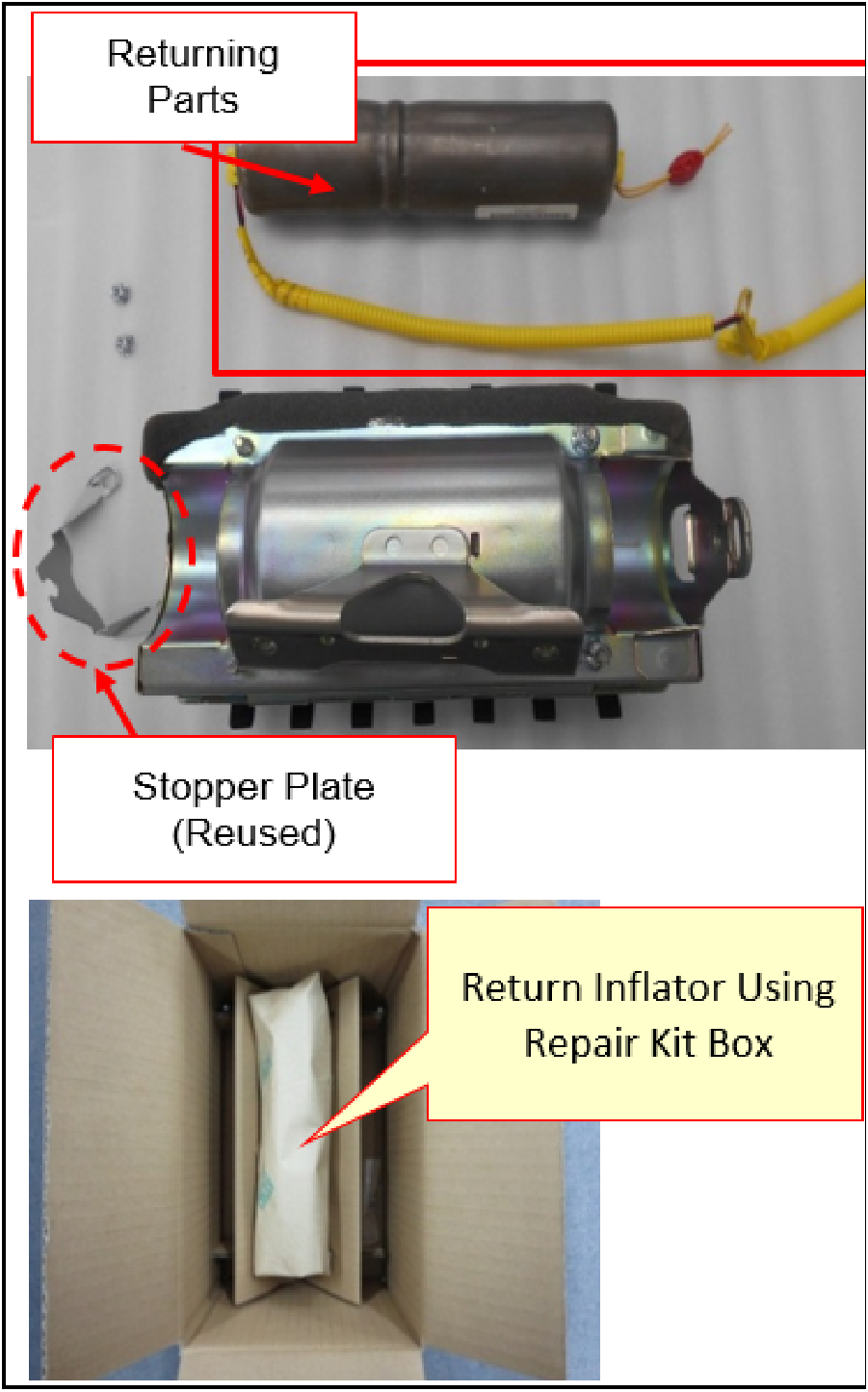
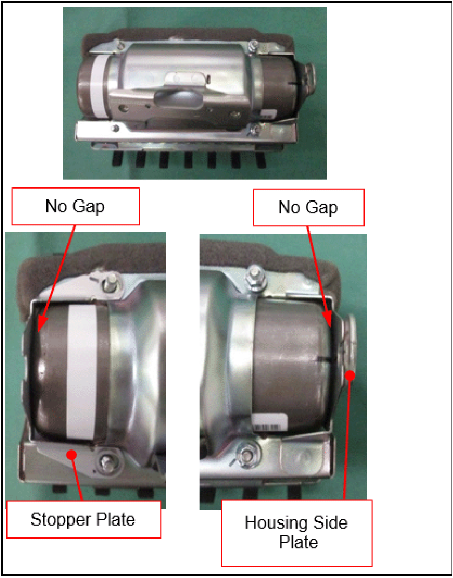
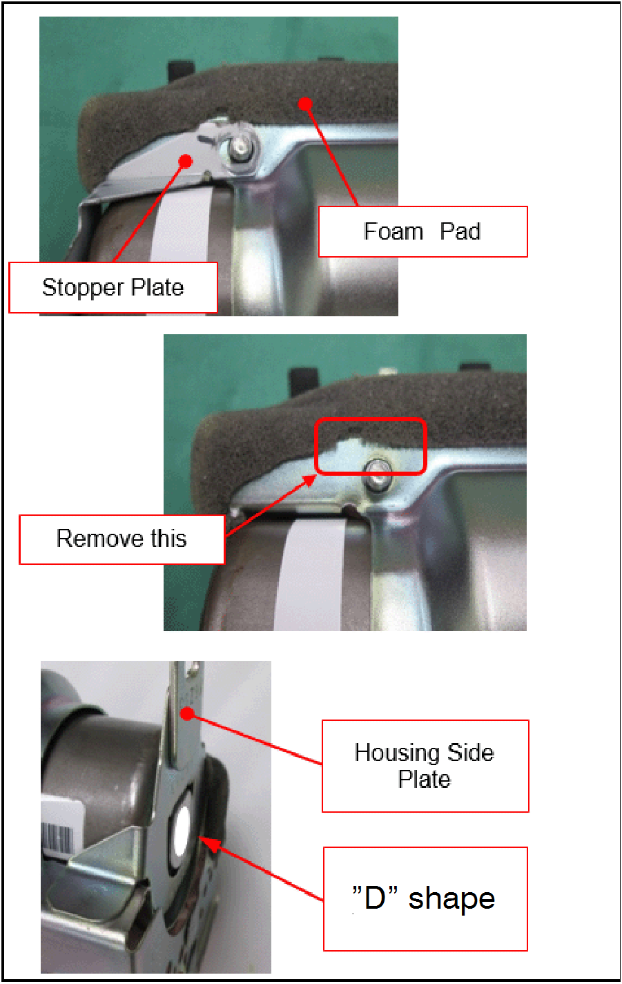
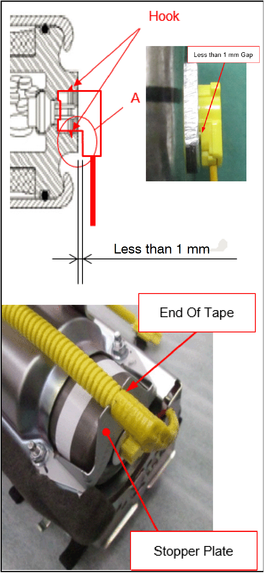
NOTE: The Stopper Plate will be reused. Do not dispose. |
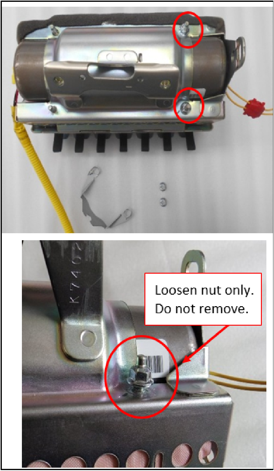 |
CAUTION: |
 |
|
 |
CAUTION: NOTE: Stopper Plate will be reused. |
INFLATOR INSTALLATION
 |
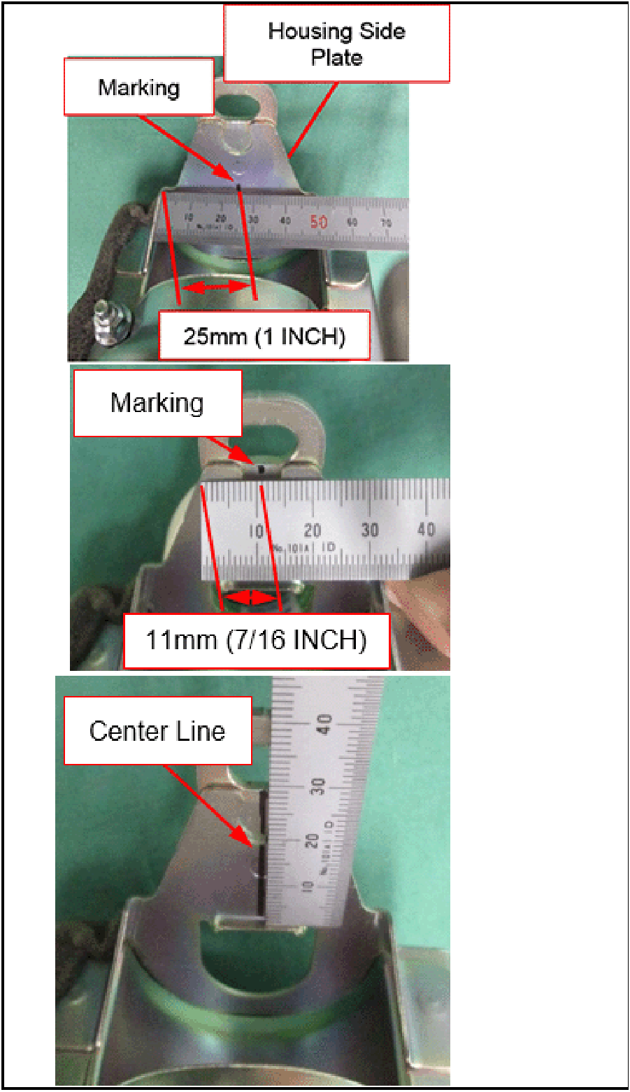
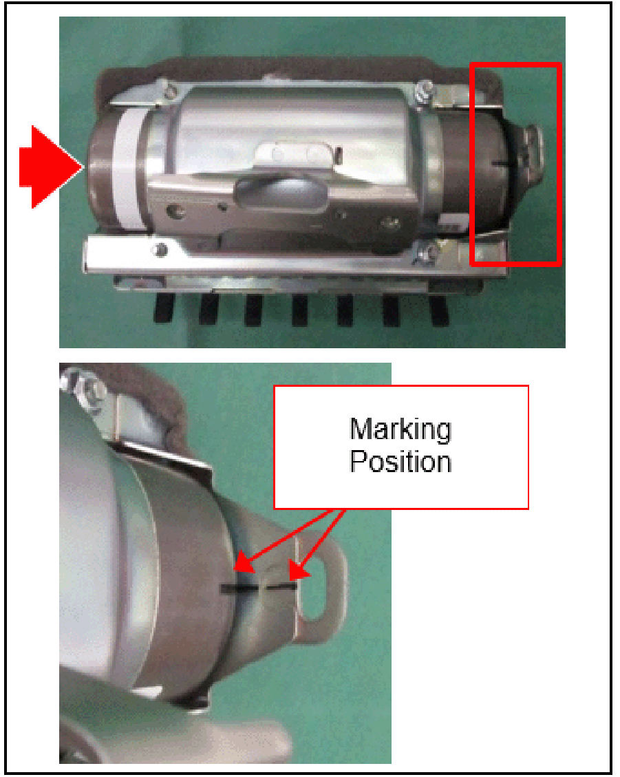
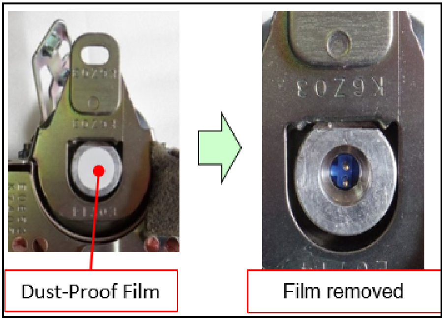
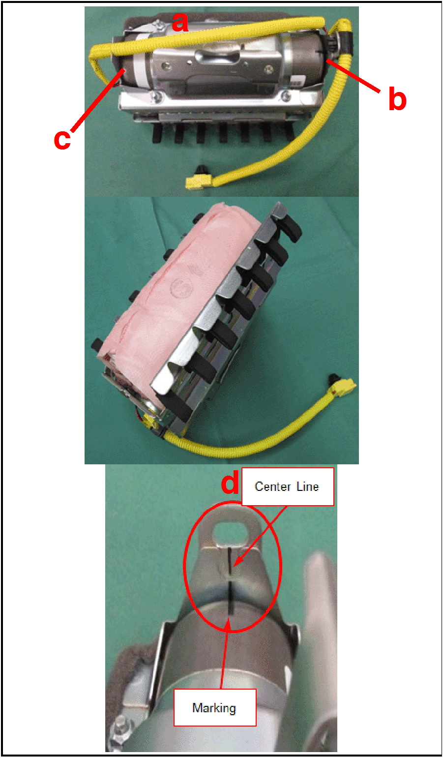
NOTE: In order to install a desiccated inflator, markings must be made on the center of the air bag module. |
 |
|
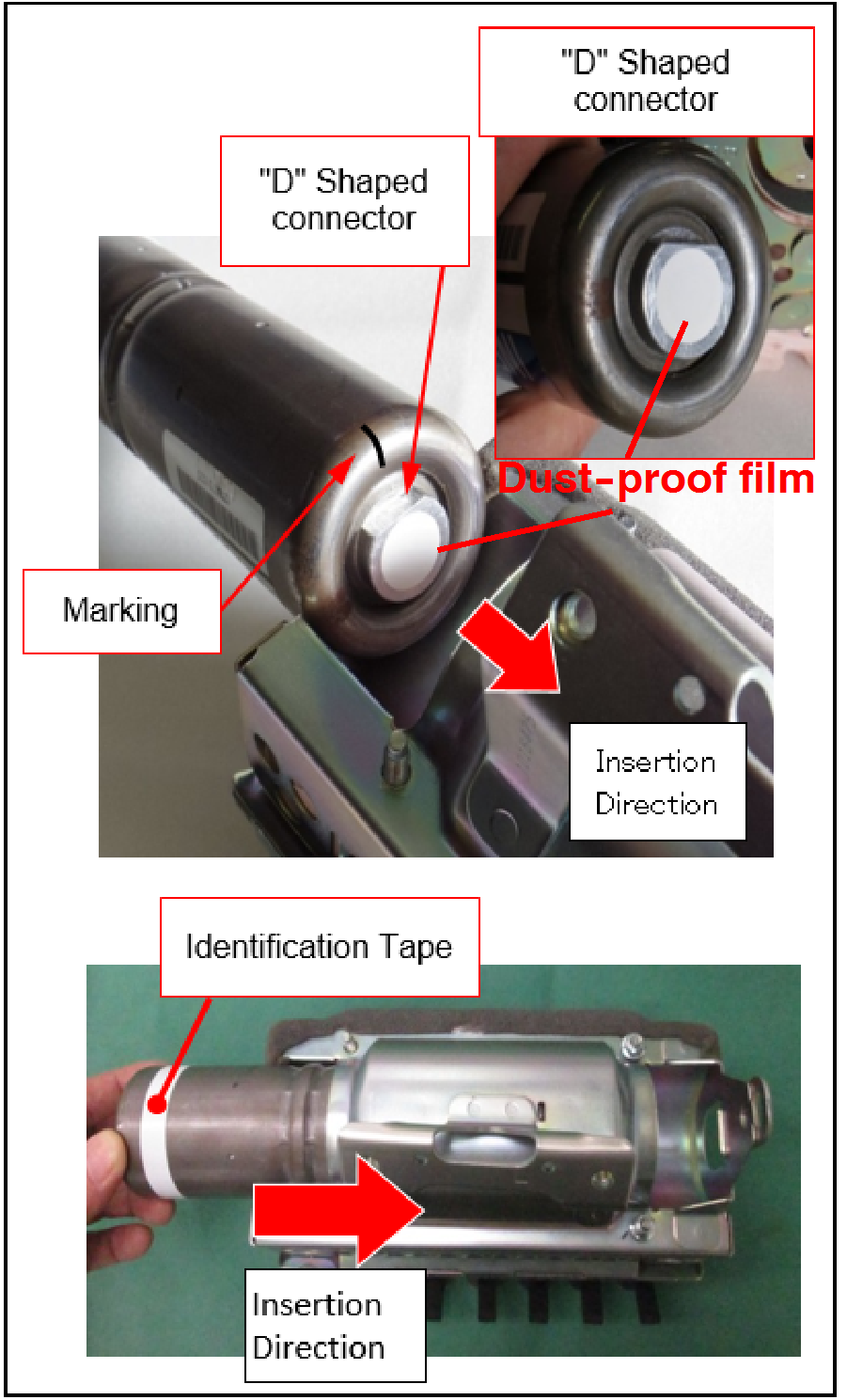 |
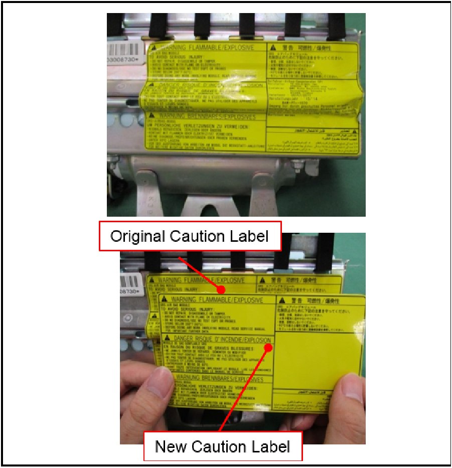
NOTE: The marking on the replacement inflator may be faint or slightly rubbed off during shipping and handling. CAUTION: |
 |
|
 |
|
 |
|
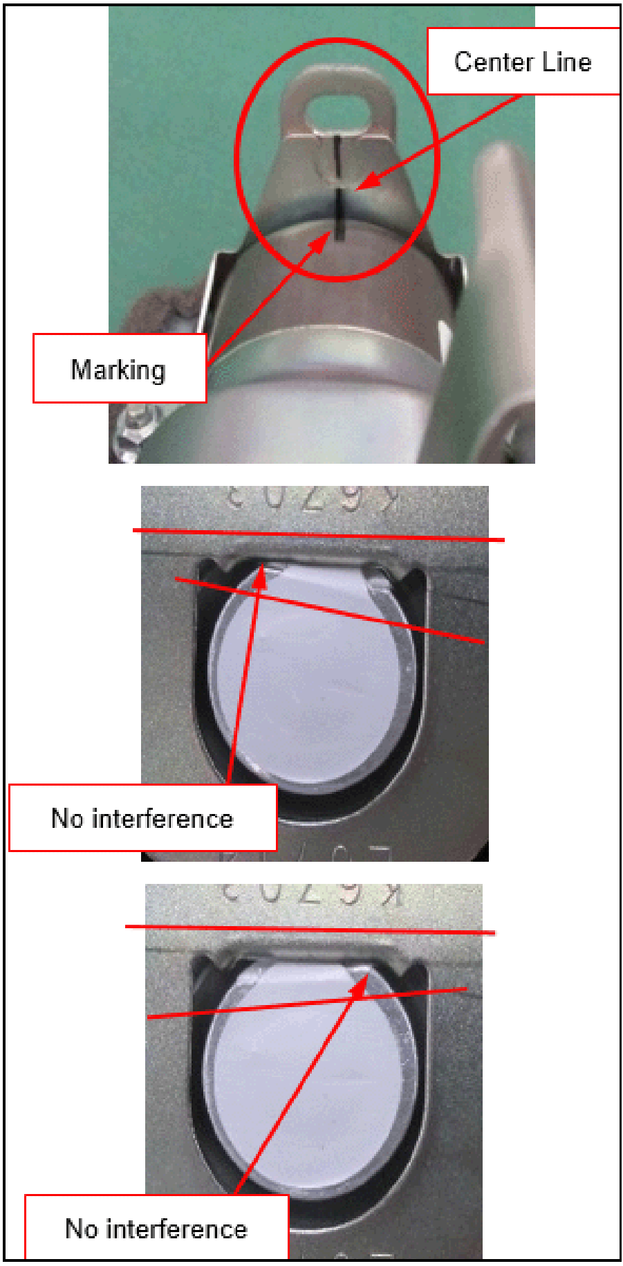 |
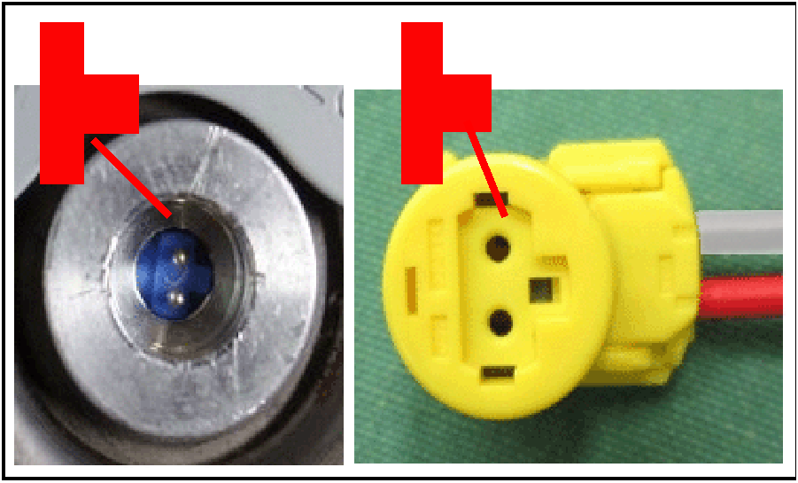
NOTE: Inflator may appear to be misaligned, as illustrated in the left photographs; however, this is acceptable as long as the Center Line and markings are aligned. |
 |
CAUTION: |
 |
|
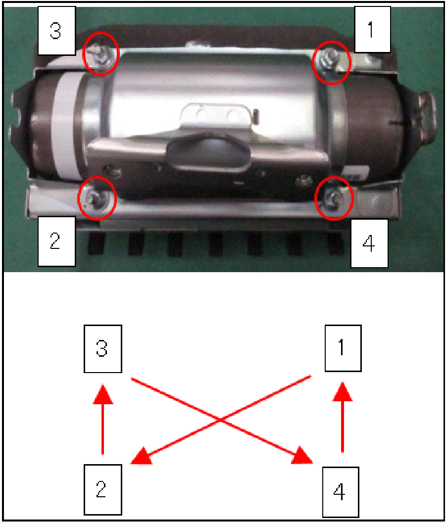 |
Specified Torque: |
 |
CAUTION: |
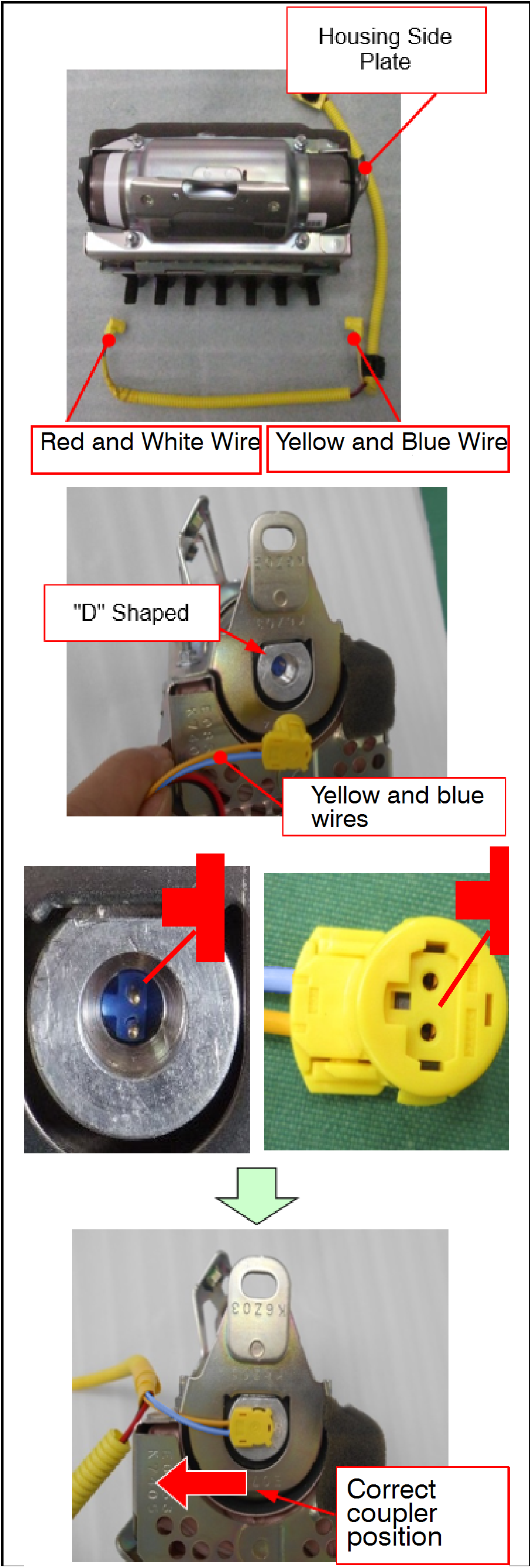 |
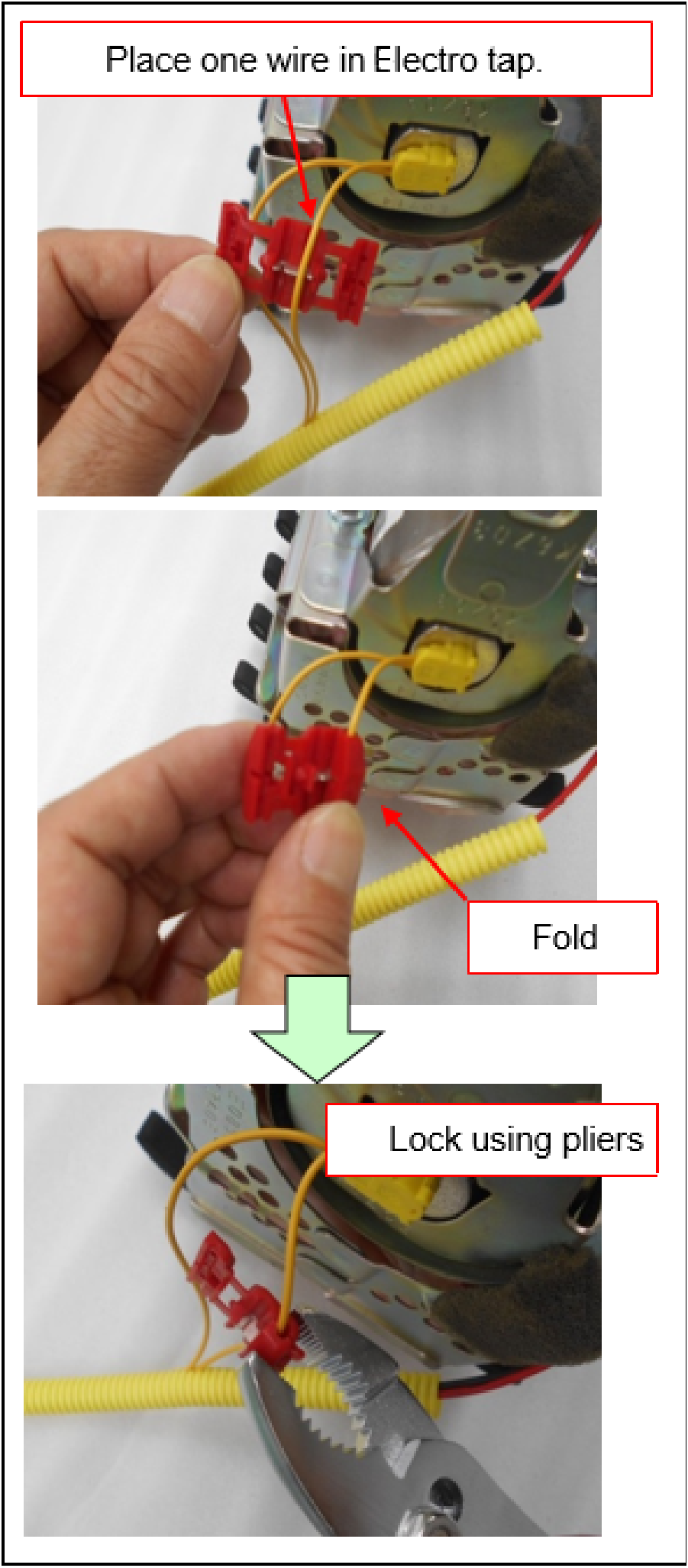
NOTE: Use the new wire harness in the repair kit. |
 |
|
 |
|
 |
CAUTION: |
 |
|
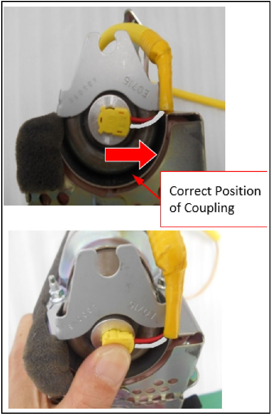 |
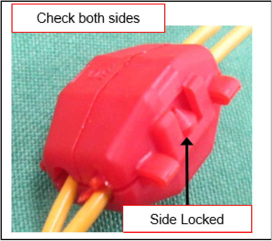
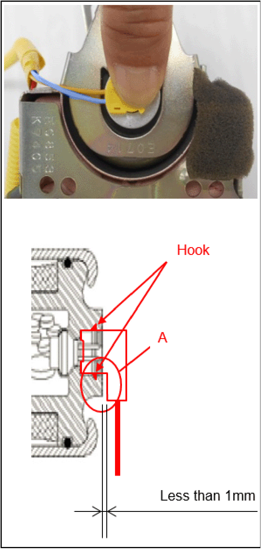
NOTE: If coupling orientation is incorrect, the connector will not securely lock into position. Reorient the coupling and try again. |
 |
NOTE: If the coupling orientation is incorrect, the connector will not securely lock into position. Reorient the coupling and try again.
|
 |
CAUTION:
|
 |
|
REINSTALLATION PROCEDURE
- Reinstall the passenger air bag module to the instrument panel.
- Reinstall the distribution duct to the instrument panel.
NOTE: Reinstall the center bolts first to align the distribution duct.
- Reinstall the instrument panel.
- Remove the electrical tape and reconnect the negative (-) battery terminal. Tighten the clamp nut securely.
- Turn the ignition switch to the “ON” position. If the “SRS” warning light illuminates continuously (does not extinguish after seven seconds), troubleshoot per the applicable service manual, Group 52B – Supplemental Restraint System (SRS) > SRS Air Bag Diagnosis > SRS Warning Light Check.
- Input radio station presets and set the clock, if applicable.
ERASE AND READ DTCs FROM ALL ECUs
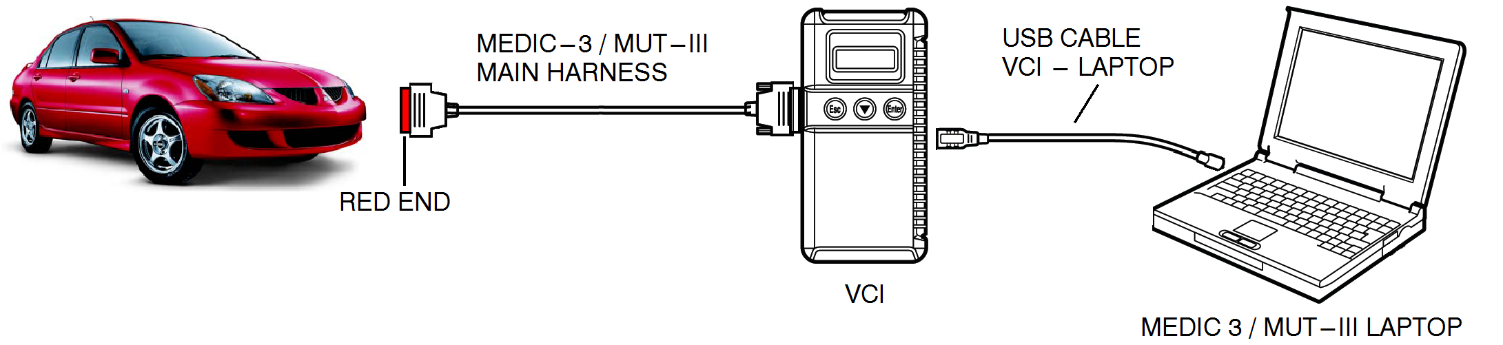
- Connect the equipment as follows:
- Turn the laptop computer/tablet on.
- Connect the USB cable to the VCI/VCI Lite.
- When the laptop displays the MUT-III main screen, connect the USB cable to the laptop.
- Connect the MUT-III main harness ‘B’ with the red or black DLC connector to the VCI/VCI Lite.
- Connect the red or black connector of the MUT-III main harness ‘B’ to the vehicle’s data link connector.
NOTE: VCI and laptop shown for illustration purposes only.
- Turn the ignition switch to the “ON” position.
NOTE: Ensure all accessories are off (e.g. lights, heating and AC system, audio/navi unit, etc…).
- From the MEDIC main page:
- Click on MUT-III.
- Select “Special Function.”
- Select “All DTCs.”
- Select “Erase and read all DTCs.” DTC 21 and 24 should appear. If any DTCs other than 21 or 24 appear, troubleshoot per the applicable service manual.
PARTS INFORMATION
Use only the Genuine Mitsubishi Parts listed below.
| Description | Part Number | Quantity |
|---|---|---|
| Kit, Air Bag Inflator | 7030A844 | 1 |
Immediately return the removed air bag inflator module to Takata utilizing the documents provided with the new part (sample attached below).
NOTE: The CCN# may be left blank.
There will not be a system generated material return request. Regardless, the campaign claim is subject to chargeback if the replaced air bag inflator is not immediately returned to Takata. Please make sure you keep a copy of proof of shipment with the repair order.
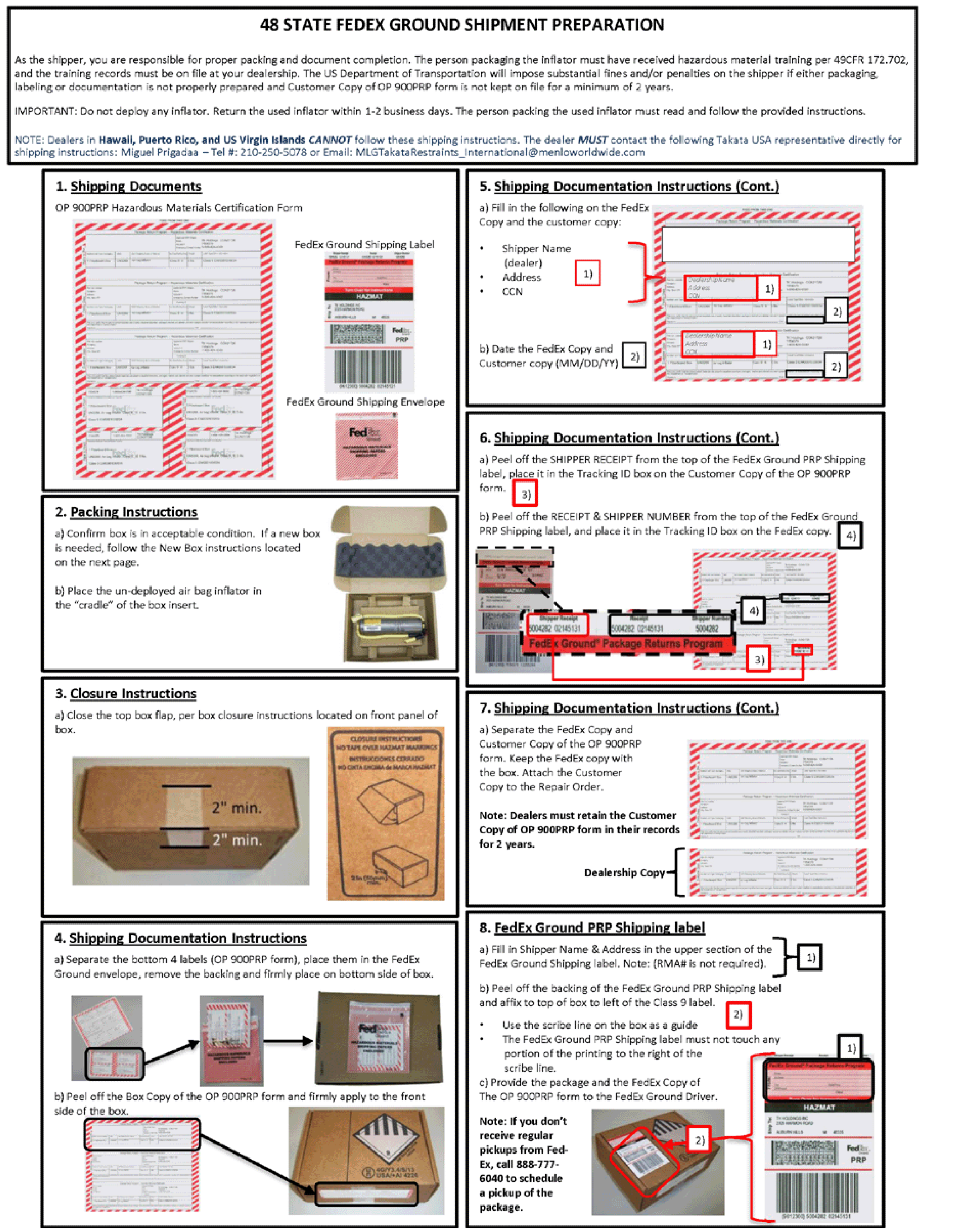
As the shipper, you are responsible for proper packing and document completion. The person packaging the inflator must have received hazardous material training per 49 CFR 172.702, and the training records must be on file at your dealership. The US Department of Transportation will impose substantial fines and/or penalties on the shipper if either packaging, labeling or documentation is not properly prepared and Customer Copy of OP 900PRP form is not kept on file for a minimum of 2 years.
Do not deploy any inflator. Return the used inflator within 1-2 business days. The person packing the used inflator must read and follow the provided instructions.
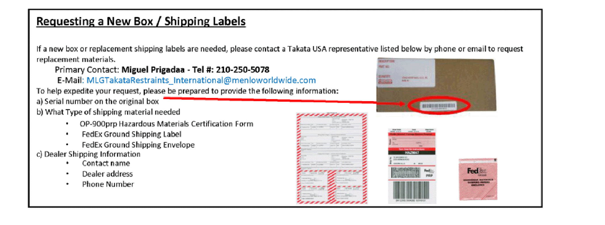
NOTE: Dealers in Hawaii, Puerto Rico, and US Virgin Islands CANNOT follow these shipping instructions. The dealer MUST contact the following Takata USA representative directly for shipping instructions: Miguel Prigadaa – Tel #: 210-250-5078
or Email: MLGTakataRestraints_International@menloworldwide.com
| DO NOT SHIP REPLACED INFLATORS TO MMNA. SHIP ONLY TO TAKATA. |
WARRANTY INFORMATION
There is only one repair scenario for this campaign.
| # | Repair Procedure | Campaign Operation |
Labor Time Allowance |
Part Number | |
|---|---|---|---|---|---|
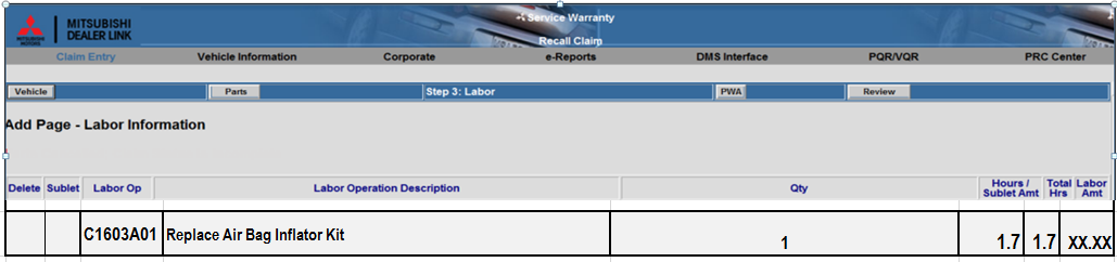
| 1 | Replace air bag inflator kit | C1603A01 | 1.7 hours | 7030A844 | |
WARRANTY / RECALL CAMPAIGN CLAIM INFORMATION
Enter all claims as claim type ‘C’ – Recall/Campaign Claims
Please follow the campaign instructions when entering each claim in order to select the applicable operation codes that correctly match up with the work that was actually performed. A claim example is provided below.
Required Operation to be performed by model year Labor Operation Labor Time
- 2006-2007 MY Lancer – Replace Air Bag Inflator Kit C1603A01 1.7 hrs.
Claim Header Section: Air Bag Inflator Replacement
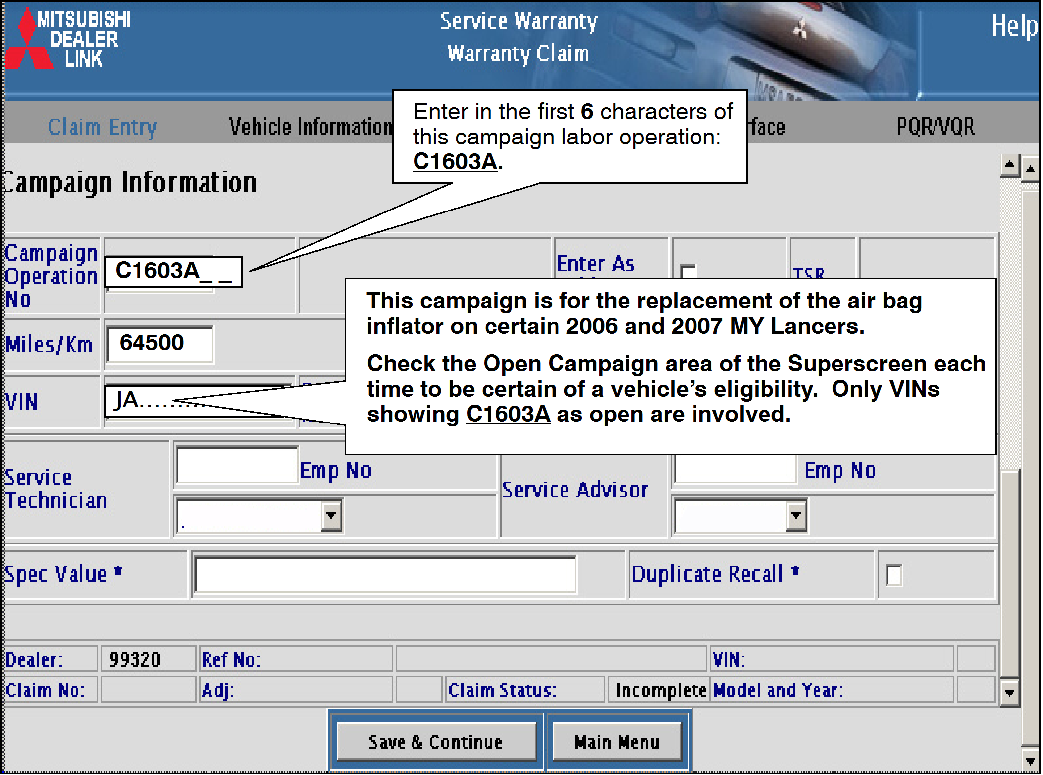
After entering the required customer data, vehicle information and applicable campaign operation number, hitting the “Save and Continue” button will automatically fill-in several fields. Please note that there is only 1 possible repair scenario for this campaign.
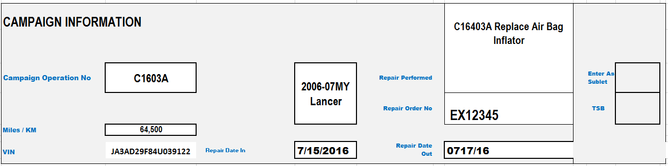
Recall Campaign Claim Example:
Follow these instructions for claim for performing the replacement of the air bag inflator.
——————————————————-
PARTS:
There is only one repair scenario and it requires the replacement of the air bag inflator.
Scenario #1 – 2006-07MY Lancer vehicles – replace the air bag inflator kit. Part# 7030A844
——————————————————-
The full service campaign labor operation number C1603A01 and the allowed labor time of 1.7 hours will be automatically entered as a result of the ‘Repair Performed’ scenario selected from the “Vehicle” page.
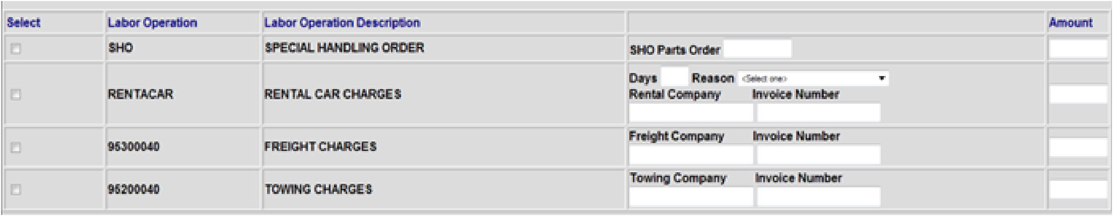
RENTAL CARS:
If there is a need to provide the owner with a rental car, claim the applicable charges in this section of the claim on the lower portion of the labor entry screen.
PARTS RETURN:
Follow the instructions in this TSB in regards to returning replaced air bag inflators. DO NOT return the replaced parts to MMNA. Failure to return a replaced inflator to Takata may result in a chargeback of the campaign claim.
 Loading...

