| “This site contains affiliate links for which OEMDTC may be compensated” |
NHTSA Campaign Number: 17V686
Manufacturer Mitsubishi Motors North America, Inc.
Components AIR BAGS
Potential Number of Units Affected 83,555
Air Bags May Not Deploy in a Crash
Air bags that do not deploy as designed in a crash increase the risk of injury.
Summary
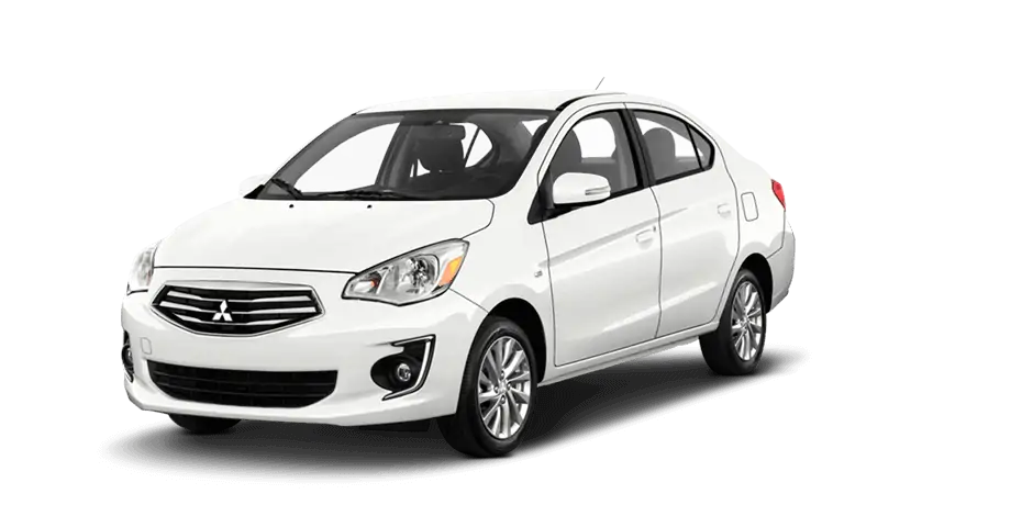
Mitsubishi Motors North America, Inc. (MMNA) is recalling certain 2014-2018 Mirage vehicles. The internal acceleration sensor in the Supplemental Restraint System (SRS) Electronic Control Unit (ECU) can misinterpret vibrations such as those from poor road conditions or a flat tire to be a sensor error thereby disabling the air bags from deploying in a crash.
Remedy
MMNA will notify owners, and dealers will reprogram the SRS-ECU software, free of charge. The recall is expected to begin in November 2017. Owners may contact MMNA customer service at 1-888-648-7820. MMNA’s number for this recall is SR-17-006.
Notes
Owners may also contact the National Highway Traffic Safety Administration Vehicle Safety Hotline at 1-888-327-4236 (TTY 1-800-424-9153), or go to www.safercar.gov.
Check if your Mitsubishi has a Recall
| SUBJECT:
MIRAGE SRS WARNING LAMP ILLUMINATION – SAFETY RECALL CAMPAIGN | No: SR-17-006 | ||||||||||||||||||
| DATE: November, 2017 | |||||||||||||||||||
| MODEL: 2014-2018 Mirage | |||||||||||||||||||
| CIRCULATE TO: | [ X ] GENERAL MANAGER | [ X ] PARTS MANAGER | [ X ] TECHNICIAN | ||||||||||||||||
| [ X ] SERVICE ADVISOR | [ X ] SERVICE MANAGER | [ X ] WARRANTY PROCESSOR | [ X ] SALES MANAGER | ||||||||||||||||
PURPOSE
This Safety Recall Bulletin provides instructions for reprogramming the SRS-ECU with a countermeasure software. The countermeasure software addresses DTCs B1557 and B1616 as a result of the SRS-ECU’s misinterpretation of vibration caused by severe road conditions and/or driving on a flat tire.
BACKGROUND
The self-diagnostic function used by the internal acceleration sensor in the SRS-ECU may misinterpret vibration caused by severe road conditions and/or driving on a flat tire to be a malfunction in the SRS-ECU. If this occurs, the SRS warning lamp will illuminate and none of the seven airbags available in the vehicle will deploy in the event of a crash.
AFFECTED VEHICLES
2014-2018 Mirage vehicles
REQUIRED OPERATIONS
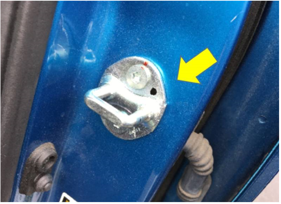
IMPORTANT: Some vehicles may have already had the recall completed at the Port. These vehicles have been marked with a black dot on the Left Front door latch. Ensure that the vehicle does NOT have a black dot on the Left Front door latch before proceeding.
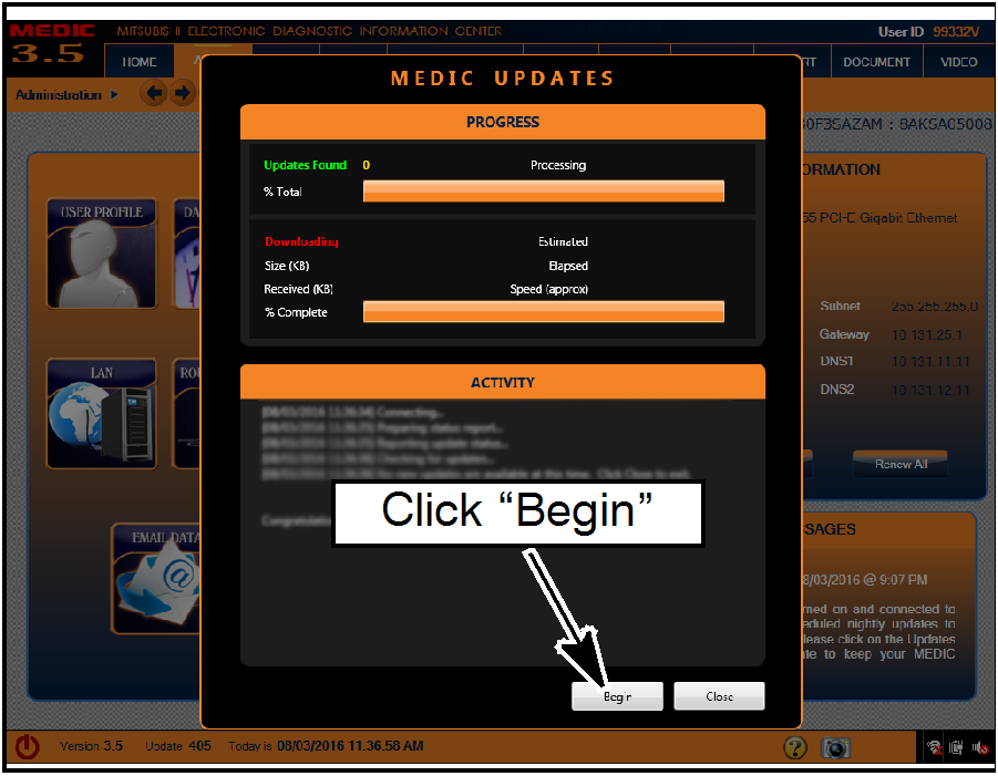
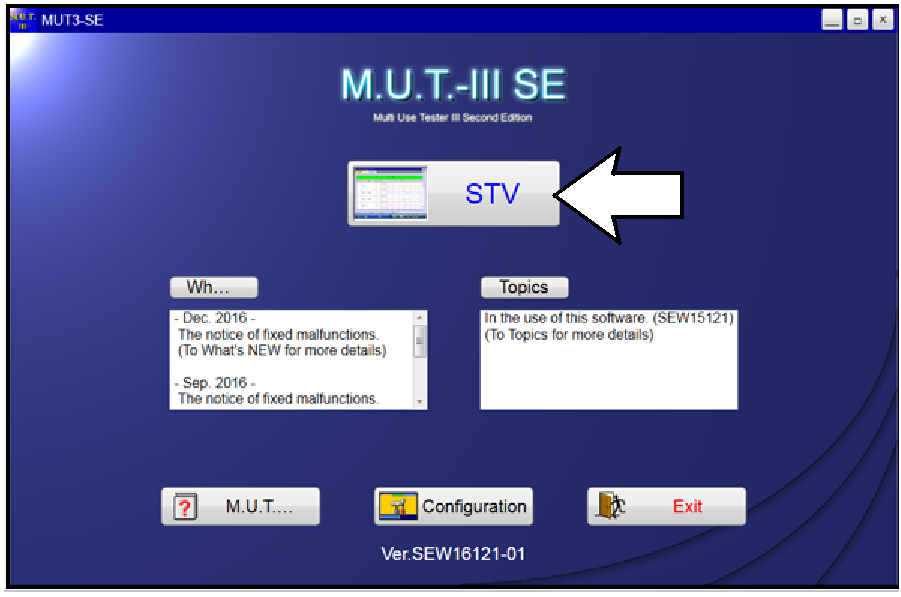
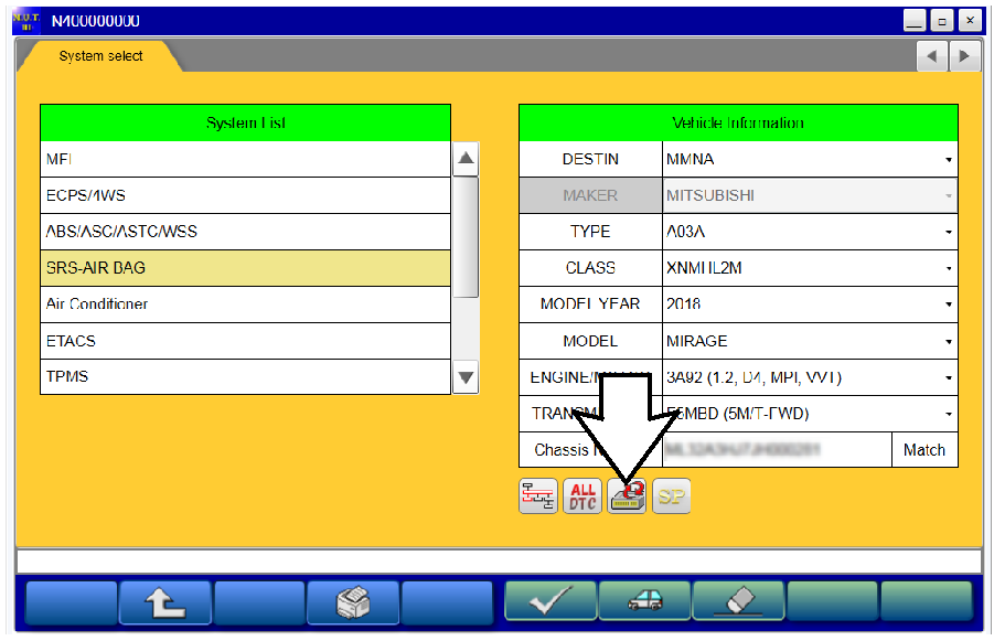
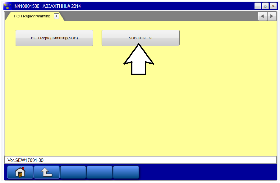
- Confirm your MUT-III is updated with the latest reprogramming database.
- Reprogram the SRS-ECU with the new software. Refer to the SRS-ECU Reprogramming Chart for new software information.
IMPORTANT: If an affected vehicle has a Malfunction Indicator Lamp (MIL) illuminated before reprogramming, and DTCs other than B1557 and B1616 are listed in the SRS memory, diagnose and repair those DTCs per the service manual before reprogramming. DO NOT reprogram the SRS-ECU until the reason(s) for DTCs other than B1557 and B1616 being set is corrected.
EQUIPMENT
The following equipment is needed to reprogram the SRS-ECU.
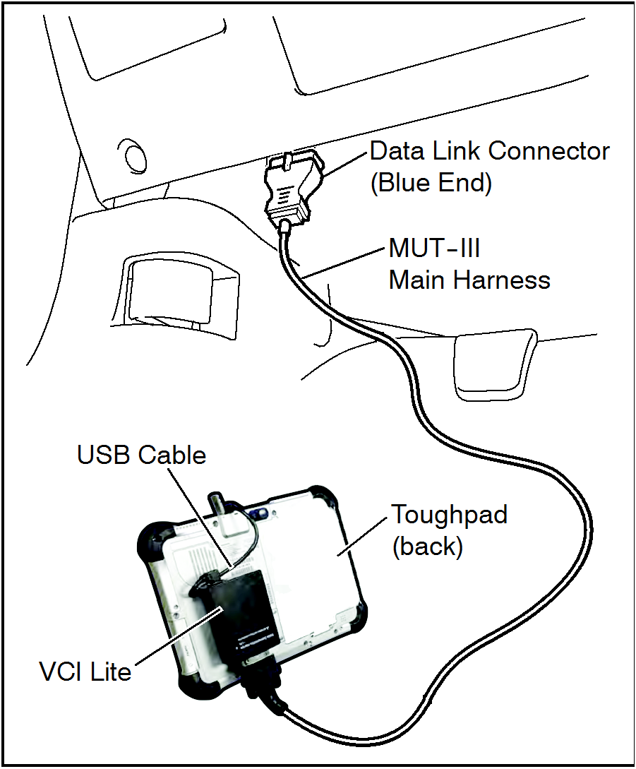
- VCI (Vehicle Communication Interface) or VCI Lite – MB991824 or MB992744V.
- MEDIC Laptop/Tablet with A/C power adapter – MIT540031, or FZG1MK2.
- MUT-III main harness ‘A’ (blue connector at the DLC end) – MB992745V.
- USB 2.0 cable – RRAR1MBR108GL.
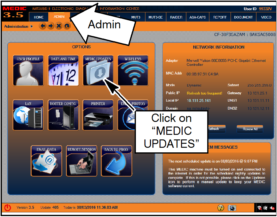
- MEDIC 3.5/4 update at 500 or higher.
- For Standalone MUT-III SE units, MUT3-SE Reprogramming Database N171001 or higher.
SRS-ECU REPROGRAMMING CHART
| M.F.F | ECU Part Number | Software Part Number | |
|---|---|---|---|
| NEW | OLD | ||
| 8635A541 | 8635A410 | 8635A410 01 | 8635A410 00 |
| 8635A540 | 8635A374 | 8635A374 01 | 8635A374 00 |
| 8635A537 | 8635A235 | 8635A235 01 | 8635A235 00 |
| 8635A539 | 8635A394 | 8635A394 01 | 8635A394 00 |
| 8635A538 | 8635A353 | 8635A353 01 | 8635A353 00 |
REPAIR PROCEDURE
- Verify that the SRS-ECU has not already been updated to the latest S/W number in the table above. If the SRS-ECU is at the latest level, reprogramming is not necessary.
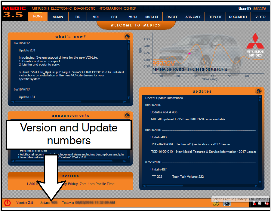 |
For MEDIC 3.5/4 users only: (MUT-III STV users go to step 5)
|
 |
|
 |
|
 |
|
 |
|
 |
|
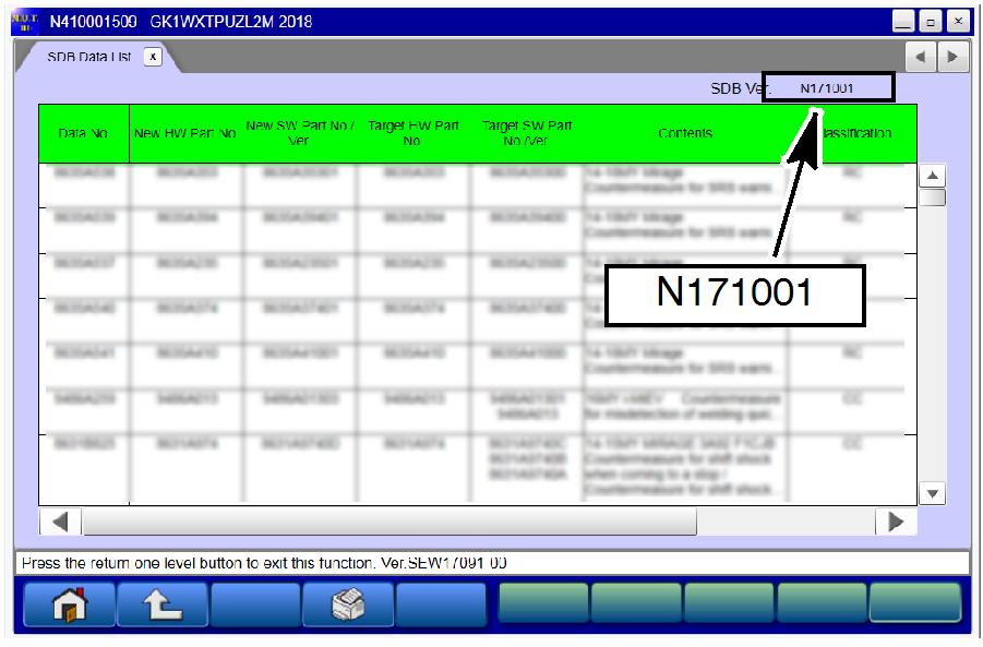 |
● If the database number displayed on your MUT3-SE is N171001 or greater, continue to the Reprogramming Procedure. ● If the reprogramming database number displayed on your MUT3-SE is lower than N171001, then the MUT3-SE database needs to be updated. |
REPROGRAMMING PROCEDURE
| NOTE: VCI Stand-alone reprogramming is not available for this procedure. The laptop/tablet and the VCI must remain connected for the entire procedure. |
 To ensure that the vehicle battery maintains 12V during the procedure, hook-up a battery charger to the vehicle during the procedure.
- Connect the equipment as follows:
NOTE: VCI Lite and MEDIC 4.0 Toughpad shown for illustration purposes only.
 |
|

| DO NOT DISTURB THE HARNESS CABLES OR CONNECTIONS DURING THE CODING PROCESS AS IT COULD CAUSE THE CONTROL UNIT TO LOSE DATA. IF THE USB CABLE IS DISCONNECTED DURING THIS PROCEDURE, A WARNING MESSAGE WILL DISPLAY. |
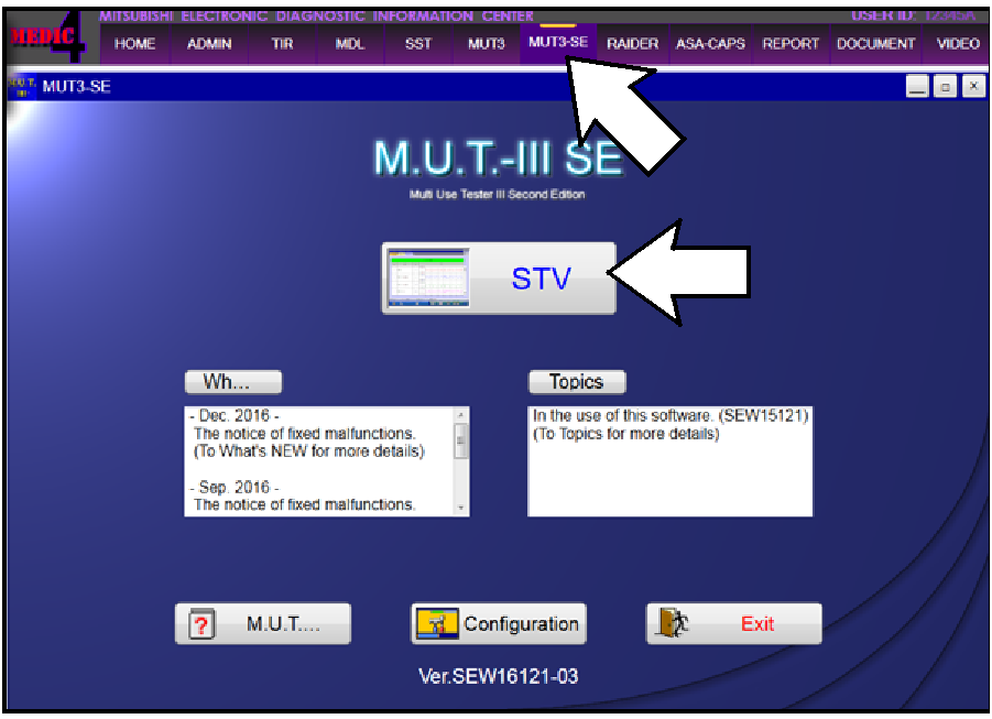
- Turn the ignition switch to the “ON” position.
 |
|
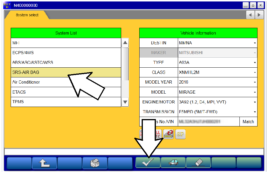
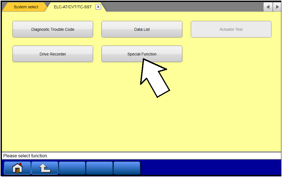
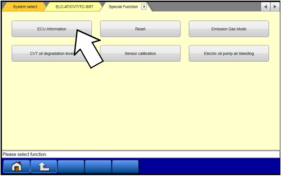
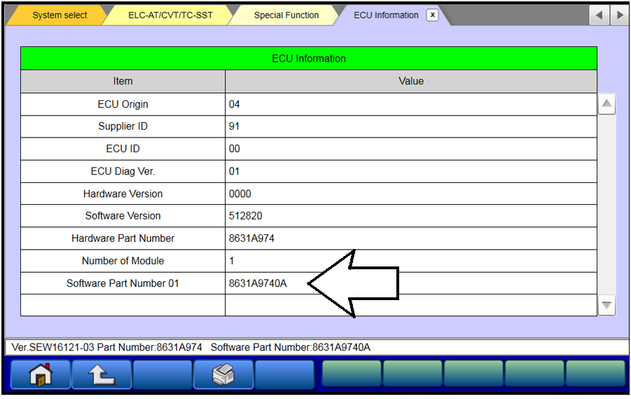
- Verify that the SRS-ECU has not already been updated to the latest S/W number in the table above.
If the SRS-ECU is at the latest level, reprogramming is not necessary.
 |
|
 |
|
 |
|
 |
|
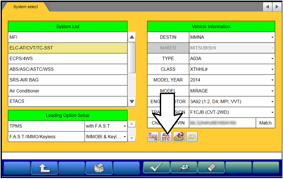
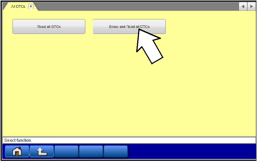
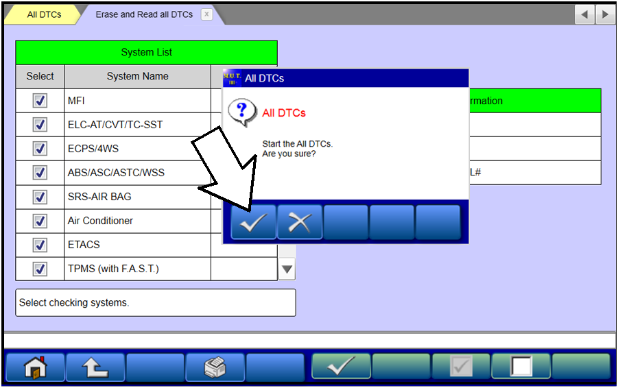
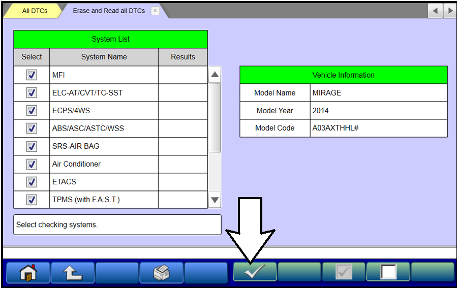
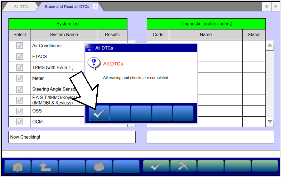
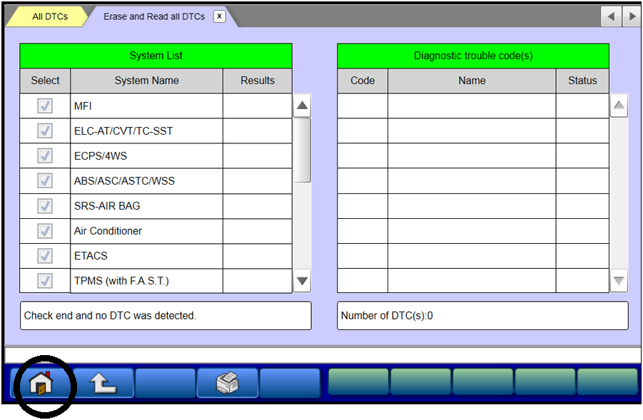
- Before reprogramming, perform an “Erase and Read All DTCs” to clear any DTCs that may have set.
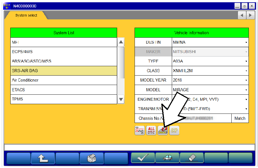
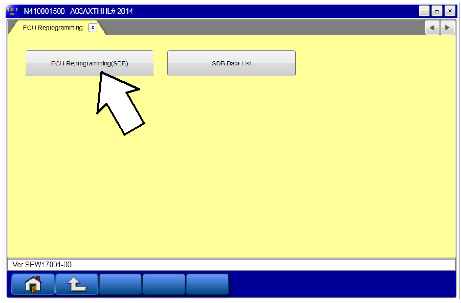
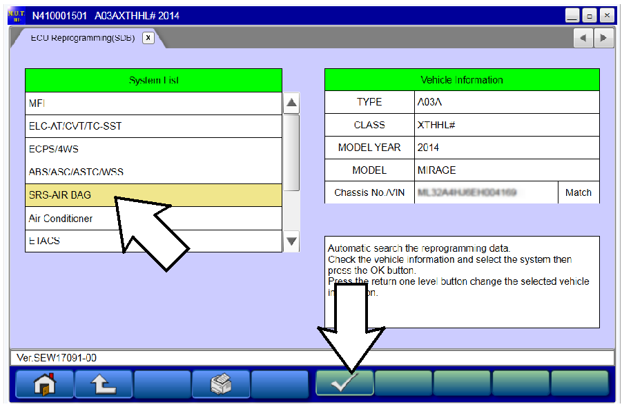
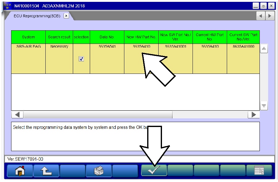
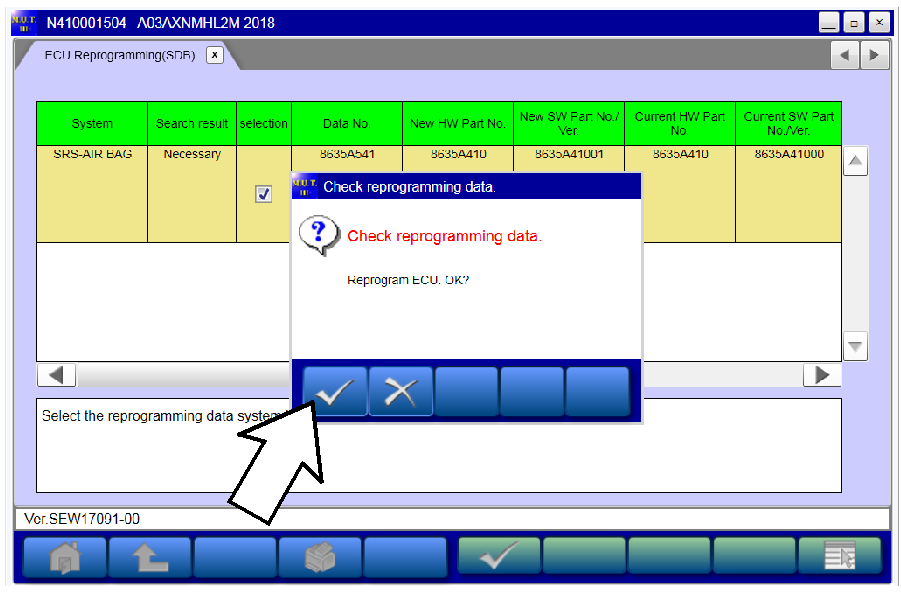
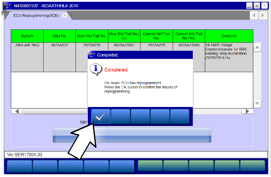
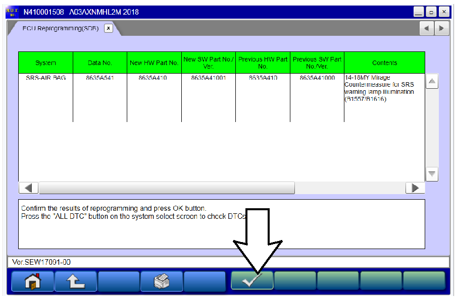
- Reprogram the SRS-ECU following the steps below.
 |
|
 |
|
 |
|
 |
|
 |
|
 |
NOTE: Do NOT disturb the cables or turn off the ignition during reprogramming. |
 |
|
 |
|
- Perform an “Erase and Read All DTCs” again to clear any DTCs that may have set.
For instructions, refer to steps 7 and 8 in this TSB. - Verify that the software Data No. is now at the latest number listed in the SRS ECU Reprogramming chart in this TSB.
For instructions, refer to step 6 in this TSB. - Turn off the ignition switch and disconnect the MUT-III. Turn off and disconnect the battery charger.
- Test drive the vehicle to confirm proper operation.
PARTS INFORMATION
No parts are required for the completion of this recall.
WARRANTY INFORMATION
There is only 1 repair scenario.
| Scenario | Involved Models | Campaign Op# | Labor Time | Repair Description |
|---|---|---|---|---|
| 1 | Certain 2014-2018 Mirage | C1706M01 | 0.4 hrs. | Reflash the SRS-ECU |
WARRANTY / RECALL CAMPAIGN CLAIM INFORMATION
Enter all claims as claim type ‘C’ – Recall/Campaign Claims.
Please follow these campaign instructions. A claim example is provided below.
Certain 2014-2018 MY Mirage
Required Operation to be performed Labor Operation Labor Time
- 2014-2018 Mirage – Reflash C1706M01 0.4 hrs.
Claim Header Section:
After entering the required customer data, vehicle information, selecting the applicable repair campaign and scenario performed (please note there is only 1 possible repair scenario for this campaign), and then hitting the “Save and Continue” button, the system will automatically fill-in several fields. See the labor and parts examples on the next page.
LABOR AND PARTS
Labor:
There is only 1 possible repair scenario for this campaign. This campaign requires only reprograming of the SRS-ECU.
Reprogram the SRS-ECU on involved vehicles:
- C1706M01 – 0.4 hrs.
Parts:
No parts are required or needed for this repair.
 Loading...
 Loading...
 Loading...
 Loading...
 Loading...
 Loading...
 Loading...
 Loading...
 Loading...
Mitsubishi Motors North America, Inc. offers J2534-1 Powertrain Control Module (PCM) re-flash capability in accordance with CARB & EPA
regulations. Mitsubishi Motors vehicles use re-flashable PCMs starting with the 1998 model year. Before attempting a re-flash of a
Mitsubishi PCM, you must obtain a validated J2534-1 pass-thru device. In addition, you must only re-flash a Mitsubishi PCM when a specific
Mitsubishi Motors Technical Service Bulletin (TSB) calls for it. All TSBs are available in the Service Information portion of this
website. In some cases, re-flash procedures are accompanied by replacement of parts or other related procedures. Failure to follow these
guidelines may result in an unsatisfactory repair.
What is J2534-1?
J2534-1 is a Society of Automotive Engineers (SAE) standard that enables the use of a J2534-1 pass-thru device (available through Special
Tool Manufacturers) and a personal computer to re-program a PCM with updated instructions, as well as perform other procedures on some
PCMs. In the case of Mitsubishi vehicles, there are two distinct families of PCMs, based on the communication protocol used for re-
flashing. Each family of PCMs requires a specific software solution available on this website as follows:
- Legacy PCMs Refer to (Reprogramming SystemIdentification) Chart for details (ISO9141) protocol for re-flash communication. A software application, Update Manager, is requiredto re-flash this type of PCM. Update Manager consists of 2 parts, Update Manager A & Update Manager B. Use Update Manager A todetermine the current PCM instruction level (current flash level), known as ROM-ID. Then use Update Manager B to re-flash the PCM withre-flash files and other support files downloaded from this website. If installed for the first time, some K-Line PCM’s require additionalinitialization procedures – for example, Immobilizer Key Code Transfer. To perform these initialization procedures, a MUT-III Special toolmust be used. Please refer to the “Special Tool” section of this webpage for details.
- The latest technology PCMs Refer to (Reprogramming SystemIdentification Chart) use CAN protocol for re-flash communication. In addition, some CAN-based PCMs require additional initializationprocedures if installed in a vehicle for the first time, such as VIN writing, Variant Coding (programming specific vehicle attributes) andImmobilizer Key Code Transfer. All procedures are done using the Pass-Thru CAN application available for download from this website. UsePass-Thru CAN Reader to obtain the PCM part number, ROM-ID (current flash level), and VIN stored in the PCM (necessary before any otherprocedures). Then download additional software components and support files to enable the Pass-Thru CAN application to perform otherprocedures as needed.
Requirements to Use J2534-1 Re-flash / Initialization Capability on Mitsubishi Motors Vehicles
- A Mitsubishi Motors Technical Service Bulletin Indicating the Need for a PCM Re-flash
As stated in the introduction, Mitsubishi Motors authorizes a PCM re-flash to be applied only in the event that such a procedure is
supported by a specific Mitsubishi Motors Technical Service Bulletin (TSB). Any PCM re-flash applied not in accordance with a TSB may
result in an unsatisfactory repair.
- A Validated J2534-1 Pass-thru Device
Because J2534-1 is an SAE standard, in theory, any J2534-1 certified device should be able to be used to perform J2534-1 re-flashes. PCM
initialization (required when replacing a Mitsubishi PCM) can be performed with the J2534-1 device with newer CAN equipped vehicles.
Legacy K-line equipped vehicles will require the MUT-III Special tool to accomplish PCM initialization (See Special Tools section). For a chart of CAN and K-Line equipped
vehicles, please refer to CAN/KLINE Chart. Several special tool
manufacturers have J2534-1 pass-thru devices available for sale. Mitsubishi Motors testing to date has found that there are some
differences between the available devices in the market. Therefore, Mitsubishi Motors can only recommend the use of devices that have been
validated to work on Mitsubishi Motors vehicles with Update Manager and Pass-Thru CAN (Mitsubishi Motors software applications to perform
PCM procedures using a J2534-1 pass-thru device).
Before using either Mitsubishi Motors J2534-1 software application, be sure to have a validated J2534-1 Pass Thru Device. Currently the
Drewtech CarDAQ-Plus (with
1.9.24 drivers) and the BOSCH MVCI (with 13.0.75.27 drivers) have been validated with Mitsubishi Vehicles. For more information on these
devices, please go to www.drewtech.com and www.boschdiagnostics.com.
Note: At this time, the Actia PassThru XS+ has not been validated with newer re-flashes.
- A Windows Based Personal Computer
A personal computer is required to host Update Manager / Pass-Thru CAN and connect to the J2534-1 Pass-thru Device. Requirements for the
computer are as follows:
- For KLINE reflashes, the Update Managers A & B softwares are only supported in Windows 2000, Windows XP Pro + SP3, andWindows 7 (32-bit) operating systems.
- For CAN reflashes, the CAN PassThru software is supported in Windows 2000, Windows XP Pro + SP3, and Windows 7 (32-bit)operating systems.
- For Windows 7 (32-bit), the CAN PassThru software and Update Manager A & B requires temporary adjustment of the UserAccount Control Settings (UAC) to enable software activation.
- To change the UAC settings in Windows 7:
| 1. Open Control Panel. |
| 2. Click on the User Accounts icon. |
| 3. Click on the User Accounts icon. This is not the same icon clicked in the previous step. This icon will be
smaller. |
| 4. Click on Change User Account Control settings. |
| 5. Remember your last setting for the slider bar and then move the slider thumb to Never notify. |
| 6. Click OK to accept the changes and reboot the PC for changes to take effect. |
| 7. After using the CAN PassThru software, return the UAC settings to your previous setting or set it to Default. Another reboot
is required for changes to take effect. |
- 256 megabytes of RAM
 (at least 256 megabytes recommended)
 - An available serial port or USB connection.
- An internet connection
- Sufficient hard drive space to install Update Manager / Pass-Thru CAN and store re-flash files & other support files (40megabyte minimum).
- Pass-thru Device Adapter Cable
Some K-Line PCMs require a special Y-cable adapter to connect the 16 pin OBD-II data-link connector from the J2534-1 pass-thru device to
both the Mitsubishi 12 or 13 pin proprietary connector & the on-board 16 pin data-link connector. This cable can be purchased through
Bosch Automotive Service Solutions (Part number MIT47295). Refer to the Adapter Cable Chart to determine which vehicles require the adapter cable.
